 |
|||
|
|
|||
|
Page Title:
Test Step 3. Disconnect the Coolant Level Sensor and Check the Supply Voltage (+5 VDC) |
|
||
| ||||||||||
|
|
 191
TM 9-2320-312-24-2
Troubleshooting Section
D. Turn the ignition key switch to the ON position.
Verify that the repair eliminates the problem. Clear
all diagnostic codes.
E. While the jumper wire is in place, access the
status screen that indicates the coolant level
STOP.
status.
Test Step 3. Disconnect the Coolant Level
Sensor and Check the Supply Voltage (+5
F. Wait for 30 seconds. Read the status and record
VDC)
the status.
G. Turn the ignition key switch to the OFF position.
A. Turn the ignition key switch to the OFF position.
Expected Result:
B. Disconnect the coolant level sensor from the
harness.
The coolant level status indicates "LOW" with the
jumper in place.
harness connector from terminal C (+ 5 VDC) to
Results:
terminal B (AP sensor/switch sensor common).
Yes Leave the jumper wire in place. If a
D. Turn the ignition key switch to the ON position.
breakout T is installed, leave the breakout T in
place also. Proceed to Test Step 6.
Expected Result:
No Proceed to Test Step 7.
The measured voltage is between 4.5 VDC and 5.5
VDC.
Test Step 5. Disconnect the Terminal for
the Sensor Supply (+5 VDC) from the
Results:
ECM Connector
Yes Proceed to Test Step 4.
No Proceed to Test Step 5.
Test Step 4. Disconnect the Coolant
Level Sensor and Check the Coolant
Level Harness
g00756042
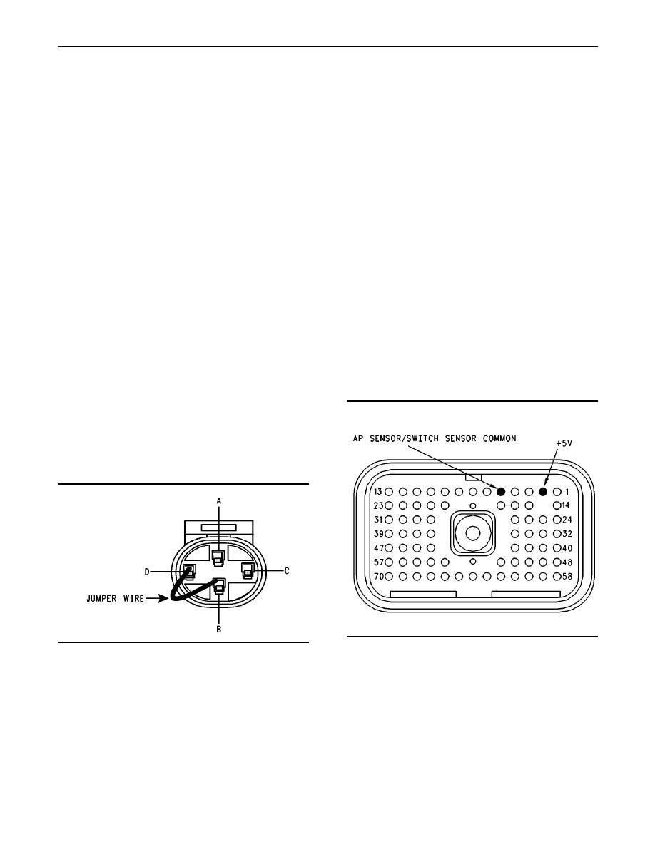
Illustration 54
g00651005
Illustration 53
Pin locations for the 4-pin sensor on the breakout T
Jumper wire
A. Turn the ignition key switch to the OFF position.
A. Turn the ignition key switch to the OFF position.
B. Disconnect the ECM vehicle harness connector
B. Disconnect the coolant level sensor from the
J1/P1.
harness.
C. Install a breakout T between ECM vehicle
C. Use a jumper wire in order to connect terminal
harness connector J1 and vehicle harness
D (coolant level normal) to terminal B (AP
connector P1.
sensor/switch sensor common) at the harness
connector.
D. Turn the ignition key switch to the ON position.
Refer to Illustration 53.
|
|
Privacy Statement - Press Release - Copyright Information. - Contact Us |
