 |
|||
|
|
|||
|
Page Title:
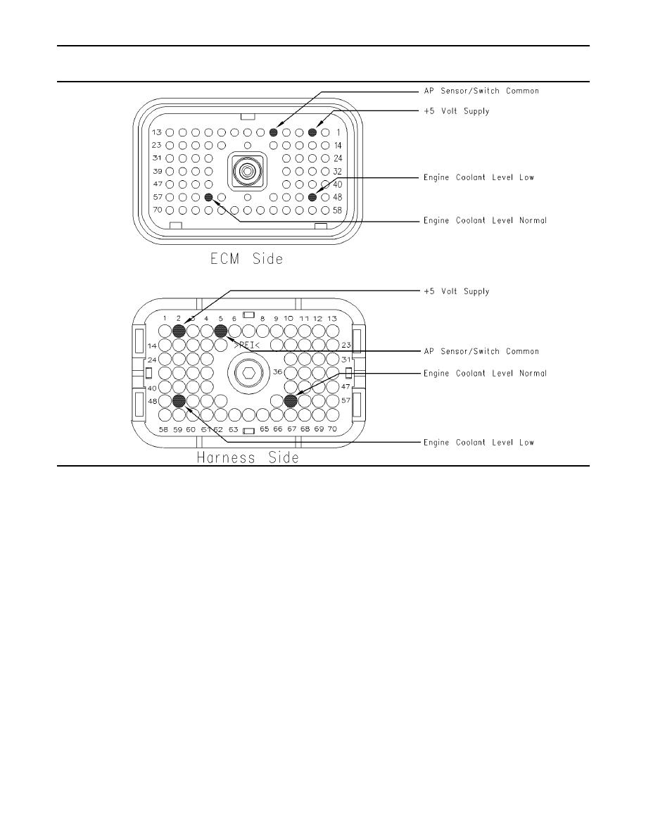
Illustration 52 Terminal locations for ECM connector P1 (4-pin sensor) |
|
||
| ||||||||||
|
|
 190
TM 9-2320-312-24-2
Troubleshooting Section
g00845671
Illustration 52
Terminal locations for ECM connector P1 (4-pin sensor)
A. Thoroughly inspect ECM vehicle harness
C. Check the ECM connector (allen head screw) for
connector J1/P1, the connector for the extension
the proper torque of 6.0 Nm (55 lb in).
harness for the coolant level and the terminals
for the coolant level sensor in the connectors.
D. Check the harness and wiring for abrasion and
The connector for the extension harness for the
pinch points from the sensor to the ECM.
coolant level connects the coolant level sensor to
the vehicle harness in the engine compartment
Expected Result:
of some chassis. Refer to Troubleshooting,
"Electrical Connectors - Inspect" for details.
All connectors, pins and sockets should be
completely coupled and/or inserted and the harness
B. Perform a 45 N (10 lb) pull test on each of the
and wiring should be free of corrosion, abrasion
wires in the ECM connector that are associated
or pinch points.
with the following connections:
Results:
P1/J1:2 +5V supply
OK Proceed to Test Step 3.
P1/J1:5 AP sensor/switch sensor common
Not OK
P1/J1:49 coolant level normal
Repair: Repair the connectors or wiring and/or
P1/J1:54 coolant level low
replace the connectors or wiring. Ensure that all
of the seals are properly in place and ensure that
the connectors are completely coupled.
Refer to Illustration 52.
|
|
Privacy Statement - Press Release - Copyright Information. - Contact Us |
