 |
|||
|
|
|||
|
Page Title:
Finding Top Center Position for No. 1 Piston |
|
||
| ||||||||||
|
|
 TM 9-2320-312-24-2
Testing and Adjusting Section
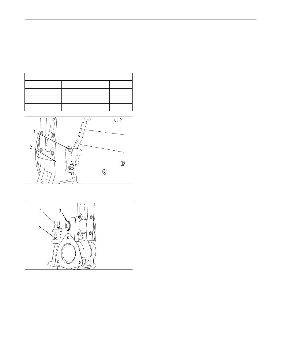
1. Remove plug (1) from flywheel housing (2). Install
i01626172
timing pin through timing hole in the flywheel
Finding Top Center Position
housing.
for No. 1 Piston
Note:
SMCS Code: 1105-531
2.
Table 4
Remove plug (3). Use the engine turning tool in
Required Tools
order to turn the engine. Do not use the eight
small bolts on the front of the crankshaft pulley.
Part Number
Description
Qty
136-4632
1
Timing Pin
Turn the flywheel in the direction of normal
engine rotation. Turn the flywheel until the timing
1
139-7064
Timing Pin Adapter
pin engages with the hole in the flywheel.
1
9S-9082
Engine Turning Tool
Note: If the flywheel is turned beyond the point of
engagement, the flywheel must be turned in the
direction that is opposite of normal engine rotation.
Turn the flywheel by approximately 30 degrees.
Then turn the flywheel in the direction of normal
engine rotation until the timing pin engages with
the threaded hole. When the No. 1 piston is at the
top center position, this procedure will remove the
play from the gears.
3. Remove the valve cover.
The inlet valves and the exhaust valve for the No.
1 cylinder are fully closed under two conditions:
g00842050
Illustration 45
No. 1 piston is on the compression stroke.
Timing Hole Location (Typical Example)
The rocker arms can be moved by hand.
If the rocker arms cannot be moved and the
valves are slightly open, the No. 1 piston is on
the exhaust stroke.
Note: Refer to Testing And Adjusting, "Crankshaft
Positions for Valve Lash Setting".
4. After the timing bolt has been installed in
the flywheel, complete these procedures, as
required:
a. Find the cylinders that need to be checked
for the stroke position of the crankshaft.
g00842034
Illustration 46
b. Find the cylinders that need to be adjusted
Timing Hole Location (Typical Example)
for the stroke position of the crankshaft.
Note: The hole for the timing pin can be in one of
5. When the actual stroke position is identified and
two positions:
the other stroke position is needed, remove the
timing bolt from the flywheel.
The right front face of the flywheel housing
(Illustration 45)
6. Turn the flywheel by 360 degrees in the direction
of normal engine rotation.
The left front face of the flywheel housing
(Illustration 46)
Note: The timing hole is used during the procedure
to set the valve lash.
|
|
Privacy Statement - Press Release - Copyright Information. - Contact Us |
