 |
|||
|
|
|||
|
|
|||
| ||||||||||
|
|
 TM 9-2320-312-24-1
FRONT AXLE ASSEMBLY REPLACEMENT - CONTINUED
0143 00
REMOVAL - CONTINUED
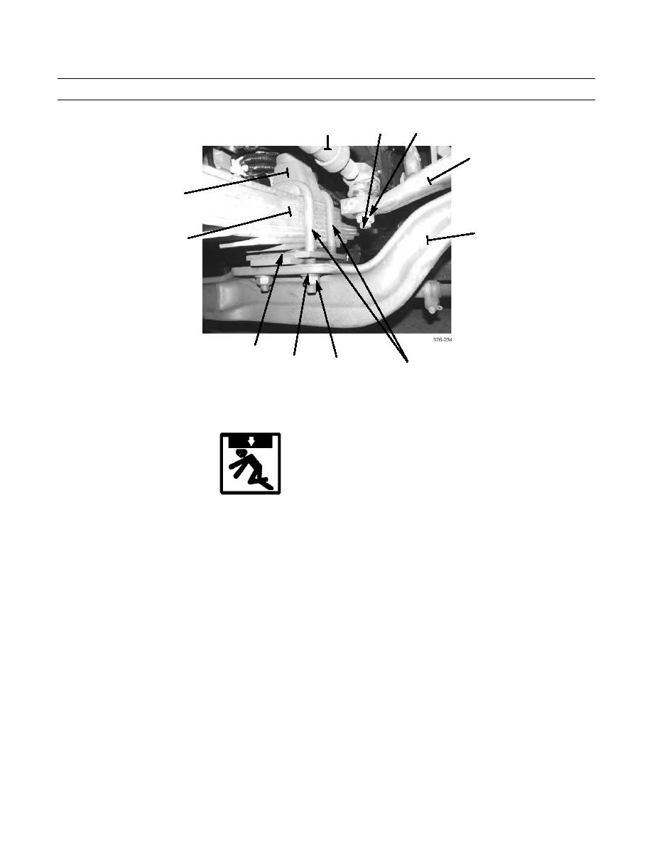
3
1
2
4
11
5
10
9
8
7
6
12.
Remove front axle steering and brake components as required (Group 080 Commercial Service Manuals).
INSTALLATION
1.
Install front axle steering and brake components as required (Group 080 Commercial Service Manuals).
WARNING
Use extreme caution when handling heavy parts. Provide adequate support and use assistance during proce-
dure. Ensure that any lifting device used is in good condition and of suitable load capacity. Keep clear of
heavy parts supported only by lifting device. Failure to follow this warning may result in injury or death to
personnel.
2.
Using floor jack centered under front axle assembly (5), position front axle assembly under vehicle, from the side of
vehicle.
3.
Position two shock absorber mounting brackets (9) on each end of axle assembly (5). Raise axle assembly until mount-
ing brackets contact underside of two springs (10).
4.
Install two spring caps (11), four U-bolts (6), washers (8), and nuts (7). DO NOT fully tighten nuts.
5.
As required, slightly raise two hydraulic jacks so that two wheel and tire assemblies can be installed. Remove floor jack
from under front axle assembly (5).
6.
Install front wheel and tire assemblies (TM 9-2320-312-10), but do not fully tighten ten lug nuts.
7.
Remove all supports from front bumper and place tires on the ground.
8.
Fully tighten wheel and tire assembly lug nuts to 500 lb-ft (678 Nm) (TM 9-2320-312-10).
9.
Fully tighten eight nuts (7) to 450 lb-ft (610 Nm).
10.
Remove nonelectrical wire and connect drag link (1) to steering arm (4).
11.
Install castle nut (3). Tighten castle nut to 250 lb-ft (339 Nm). Install new cotter pin (2).
0143 00-3
|
|
Privacy Statement - Press Release - Copyright Information. - Contact Us |
