 |
|||
|
|
|||
|
|
|||
| ||||||||||
|
|
 TM 9-2320-312-24-1
FIFTH WHEEL LIFT HYDRAULIC HOSES AND FITTINGS REPLACEMENT
AND LIFT CYLINDER HEAD CAP AND ROD PACKING TIGHTENING - CONTINUED
0127 00
HOSE INSTALLATION - CONTINUED
4.
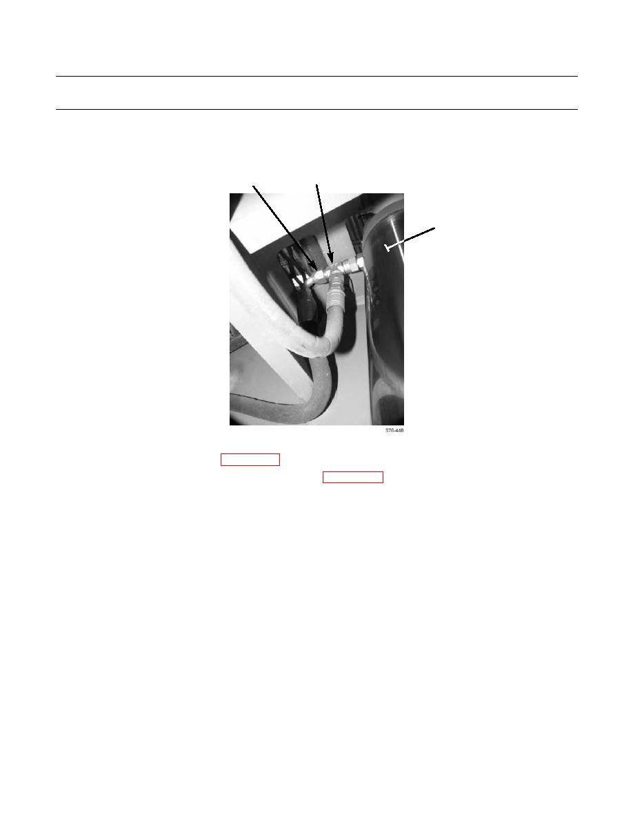
Connect hose (1) to tee (2) at right-side lift cylinder (3).
2
1
3
5.
Place battery disconnect switch in ON position.
6.
Fill hydraulic reservoir as required (WP 0129 00). Be alert for evidence of leaks.
7.
Install transmission access cover and rear platform grating (WP 0039 00).
TIGHTENING LIFT CYLINDER HEAD CAP AND ROD PACKING
NOTE
If the following procedure does not eliminate leakage from lift cylinder head caps, cylinder will require
replacement.
1.
Fully raise fifth wheel (TM 9-2320-312-10).
CAUTION
Ensure block of wood is placed so as not to come in contact with fittings at top of rear air reservoir. Failure
to do so may damage fittings.
2.
Place a block of wood across frame, to provide support for fifth wheel frame sub-assembly (13). Lower fifth wheel
frame sub-assembly onto block of wood.
3.
Shut down engine. Operate fifth wheel lift control to relieve hydraulic pressure in cylinders (TM 9-2320-312-10).
4.
Back out setscrew (10) on cap (11) a few turns.
5.
Use a strap wrench to hold rod sleeve.
6.
Insert blade of spanner wrench into cap spanner slot (12). Tighten clockwise until there is no looseness in cap (11).
0127 00-6
|
|
Privacy Statement - Press Release - Copyright Information. - Contact Us |
