 |
|||
|
|
|||
|
Page Title:
ELECTRICAL CONNECTOR REPAIR - CONTINUED |
|
||
| ||||||||||
|
|
 TM 9-2320-312-24-1
ELECTRICAL GENERAL MAINTENANCE INSTRUCTIONS - CONTINUED
0120 00
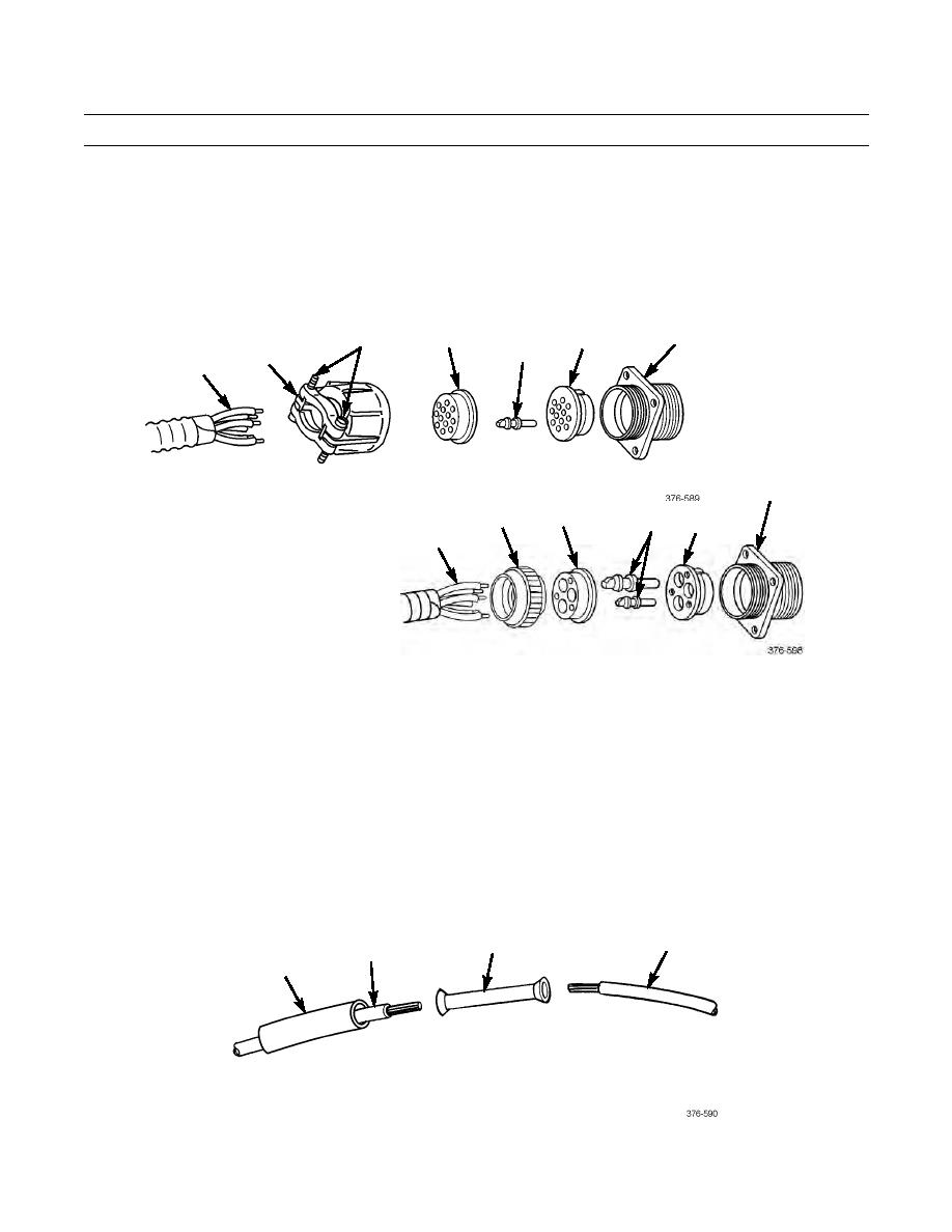
ELECTRICAL CONNECTOR REPAIR - CONTINUED
8.
Push insert (15) into shell (16) from rear until seated. Groove in insert must be aligned with guide in shell to ensure
proper fit
9.
Push pins (14) into insert (15) from rear until seated.
10.
Push grommet (13) down wires (10) and over solder wells of pins (14).
11.
Install nut (11) onto shell (16).
12.
If repairing a trailer electrical connector, tighten two screws (12).
16
12
15
13
14
11
10
16
11
13
14
15
10
SPLICING WIRES
NOTE
The use of high quality splice connectors is essential to ensure optimum electrical integrity. Use the type and
size connector best suited to the application.
1.
Inspect each end of wire (18). Trim wire back, as necessary, to ensure undamaged ends.
2.
Using wire stripping tool, strip insulation of wires (18) to expose length of metal strands suitable for size of splice con-
nector (19).
3.
Cut length of insulation sleeving (17) at least 3/4 in longer than length of splice connector (19) and slide insulation
sleeving over one wire (18).
4.
Insert each wire (18) into splice connector (19) and crimp connector to metal strands AND insulation of wire.
5.
Center insulation sleeving (17) over splice connector (19) and use heat gun to shrink insulation sleeving.
18
19
18
17
0120 00-3
|
|
Privacy Statement - Press Release - Copyright Information. - Contact Us |
