 |
|||
|
|
|||
|
Page Title:
POWER STEERING HYDRAULIC HOSES AND FITTINGS REPLACEMENT |
|
||
| ||||||||||
|
|
 TM 9-2320-312-24-1
POWER STEERING HYDRAULIC HOSES AND FITTINGS REPLACEMENT
THIS WORK PACKAGE COVERS
Removal, Installation
INITIAL SETUP
Maintenance Level
Materials/Parts
Cap set, protective (Item 6, WP 0165 00)
Unit
Fluid, hydraulic, petroleum base (Item 25 or 26,
MAC Reference
Rag, wiping (Item 51, WP 0165 00)
Group 110
Strap, tiedown (Item 57, WP 0165 00)
RPSTL Reference
Tag, marker (Item 58, WP 0165 00)
Group 110, Figure 4
Nut, lock (P/N NE11-048-21)
Tools and Special Tools
References
TM 9-2320-312-10
Tool kit, general mechanic's (Item 35, WP 0166 00)
Shop equipment, common no. 1 (Item 28, WP 0166
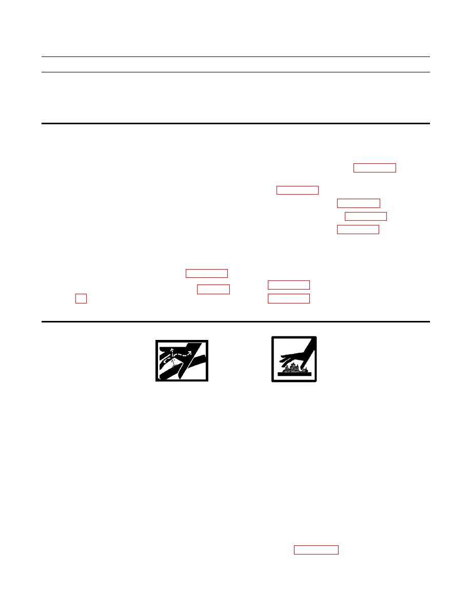
WARNING
DO NOT disconnect or remove any hydraulic system line or fitting unless hydraulic system pressure
has been relieved. Tighten all connections before applying pressure. Escaping hydraulic fluid under
pressure can penetrate the skin, causing serious injury.
Search for leaks with a piece of cardboard. Protect hands and body from high-pressure fluids. If an acci-
dent occurs, see a doctor immediately. Any fluid injected into the skin must be surgically removed
within a few hours or gangrene may result.
At operating temperature, hydraulic fluid is hot. Allow hydraulic fluid to cool before disconnecting any
hydraulic lines. Failure to do so could result in serious burns.
Hydraulic fluid is very slippery. Immediately wipe up any spills. Failure to follow this warning may
result in injury to personnel.
NOTE
This work package describes replacement of hydraulic hoses between power steering pump on left side
of engine and power steering gear at left frame rail at front of vehicle.
Diagram of power steering hydraulic system is located in Figure 3 in WP 0137 00 (Diagrams).
|
|
Privacy Statement - Press Release - Copyright Information. - Contact Us |
