 |
|||
|
|
|||
|
|
|||
| ||||||||||
|
|
 TM 9-2320-312-24-1
THROTTLE POSITION SENSOR (TPS) ASSEMBLY REPLACEMENT - CONTINUED
0014 00
REMOVAL - CONTINUED
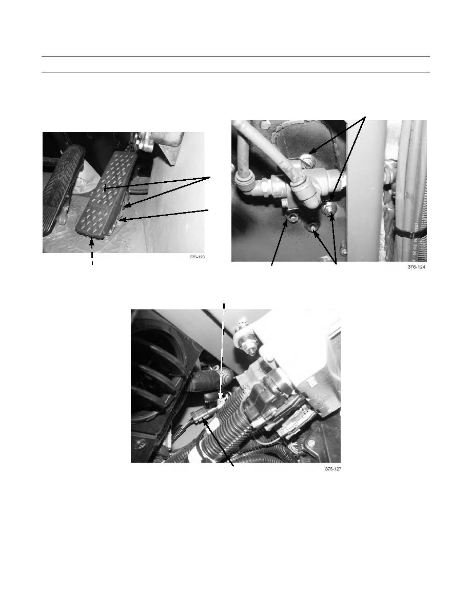
3.
Remove four nuts (3) from bolts (2) under cab.
4.
Remove throttle position sensor assembly (1) from floor of cab.
3
1
2
2
3
3
5.
Trace wiring harness of throttle position sensor assembly (1) back to connection point under instrument panel. Discon-
nect connector (5) from vehicle wiring harness connector (4).
4
5
INSTALLATION
1.
Connect throttle position sensor assembly connector (5) to vehicle wiring harness connector (4).
2.
Install throttle position sensor assembly (1) to floor of cab with four bolts (2) and nuts (3).
3.
Place battery disconnect switch in ON position.
4.
Lower cab (TM 9-2320-312-10).
5.
Start engine (TM 9-2320-312-10). Ensure throttle position sensor assembly functions properly.
END OF WORK PACKAGE
0014 00-2
|
|
Privacy Statement - Press Release - Copyright Information. - Contact Us |
