|
| |
TM 9-2320-304-14&P
4-225
Organizational Maintenance Instructions (Cont)
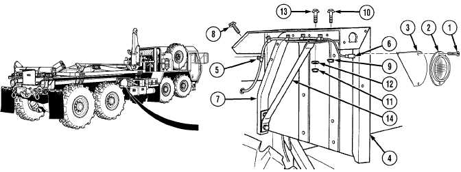
a. Removal.
NOTE
·
Both rear fenders are removed the same way. The right fender is shown.
·
Mark all wires before disconnecting.
(1) Remove two screws (1), reflector (2), and reflector bracket (3) from fender (4).
(2) Remove six push clips (5) and marker lamp wiring harness (6) from fender support arm (7).
(3) Remove self-tapping screw (8) from fender support arm (7). Discard self-tapping screw.
(4) Remove two locknuts (9) and screws (10) from fender support arm (7). Discard locknuts.
(5) Remove locknut (11), washer (12), and screw (13) from fender support arm (7) and fender
brace (14). Discard locknut.
(6) Remove rear fender (4) from fender
support arm (7).
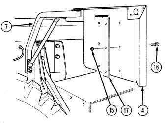
(7) Remove four locknuts (15), screws (16),
and two braces (17) from rear fender (4).
Discard locknuts.
|