|
| |
TM 9-2320-304-14&P
4-172
Organizational Maintenance Instructions (Cont)
4-35. PROXIMITY SWITCH REPLACEMENT/ADJUSTMENT (HOOK ARM DOWN)
(CONT).
NOTE
Tag all wires prior to removal.
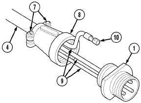
(4) Loosen two screws (7) and remove
nut (8) from MC88 connector (1).
(5) Remove three wires (9) with
terminals (10) from MC88 connector (1).
(6) Remove nut (8) and MC 88 connector (1)
from proximity switch (4).
b. Installation.
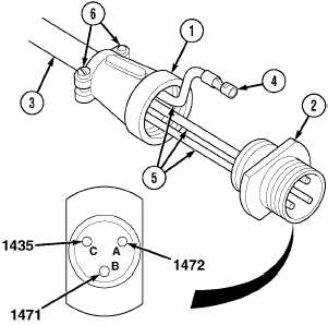
(1) Position nut (1) and MC88 connector (2)
on proximity switch (3).
(2) Install three terminals (4) with wires (5)
in MC88 connector (2) in the following
positions:
Wire
Position
Color
1472
A
Brown
1471
B
Black
1435
C
Blue
Table 4-5. Proximity Switch Wire Positions
(3) Install nut (1) on MC88 connector (2)
and tighten two screws (6).
NOTE
Serrated side of nuts face bracket.
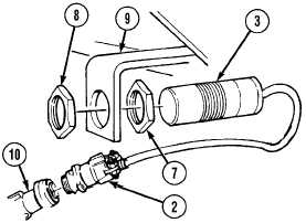
(4) Install nut (7) on proximity switch (3).
(5) Install proximity switch (3) and nut (8)
on compression frame (9).
(6) Install proximity switch MC88
connector (2) on main harness
connector (10).
|