 |
|||
|
|
|||
|
Page Title:
Assemble the Differential and Gear |
|
||
| ||||||||||
|
|
 TM 9-2320-303-24-2
REAR-REAR AXLE DIFFERENTIAL CARRIER REPAIR - CONTINUED
0259 00
DIFFERENTIAL CARRIER ASSEMBLY - CONTINUED
Assemble the Differential and Gear.
e.
CAUTION
The ring gear should not be pressed or driven on the case, as this would cause excessive metal particles to
lodge between the gear and case, thus resulting in gear run-out. Proper installation should, therefore, incor-
porate preheating the gear to assure correct interference fit and to eliminate metal pickup.
(1)
Heat the ring gear (8) in oil to approximately 160F-180F (71.1C-82.2C) for about ten minutes before
assembly.
(2)
Install twelve new bolts, washers, and nuts. Torque to 180-230 lb-ft (244-312 Nm).
(3)
Pre-lubricate the differential case inner walls and all component parts with the recommended axle lubri-
cant.
(4)
Position the thrust washer (5) and side gear (6) in the gear case (10) half.
(5)
Place the spider (7) with pinions (23) and thrust washers (22) in position.
(6)
Install the second side gear (6) and thrust washer (5).
(7)
Position the other case (4) half over the assembly, alining match marks of both halves. Draw the assembly
together with three equally spaced washers (3) and capscrews (2).
(8)
Install the remaining washers (3) and capscrews (2 and 24) and torque to 85-115 lb-ft (115-156 Nm).
(9)
If new bearings are to be used, press squarely and firmly on the differential case halves with a suitable
sleeve.
f.
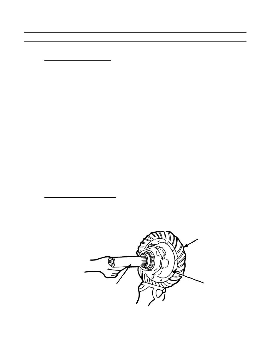
Rolling Resistance of Differential Nest.
(1)
Place the differential and ring gear (8) assembly in a vise with soft metal jaws.
(2)
Insert a checking tool (made from a splined axle shaft end) into the differential nest (fig. 3). Allow the
splines of the tool to engage with the spline of one side gear (6) only.
8
DIFFERENTIAL
NEST
CHECKING TOOL
402-712
Figure 3. Install the Checking Tool.
0259 00-8
|
|
Privacy Statement - Press Release - Copyright Information. - Contact Us |
