 |
|||
|
|
|||
|
|
|||
| ||||||||||
|
|
 TM 9-2320-303-24-2
TRANSMISSION OVERHAUL - CONTINUED
0248 00
ASSEMBLY
Use extreme caution when handling heavy parts. Provide adequate support and use assistance during proce-
dure. Ensure that any lifting device used is in good condition and of suitable load capacity. Keep clear of
heavy parts supported only by lifting device. Failure to follow this warning may result in death or injury to
personnel.
NOTE
Ensure all transmission components are cleaned and well lubricated before reassembling transmission
assembly.
Before beginning assembly, attach bracket (J41445) and holding fixture (J35926) to main transmission
housing. Use a suitable hoist to mount fixture and housing on a repair stand.
Ensure main housing is horizontal when installing C3/C4 clutch Module.
Installation of C3/C4 Clutch Assembly
1.
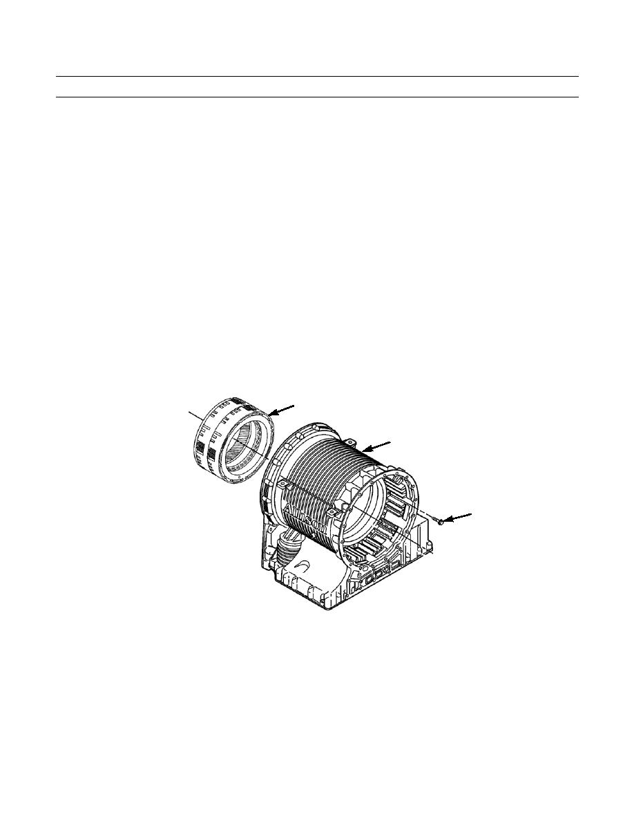
Install C3/C4 clutch assembly (51) through input end of main housing (24), aligning bolt holes in clutch assembly with
holes in main housing.
2.
Install two bolts (52), 180 degrees from each other, to hold clutch in place.
3.
Rotate transmission housing on stand and install remaining 12 bolts (52). Tighten bolts to 38-45 lb-ft (51-61 Nm).
51
24
52
402-605
Installation of Rotating Clutch Module and Front Support and Charging Pump Module
1.
Install an M16 eye bolt into turbine shaft (49). Using a suitable hoist, install rotating clutch module (50) into main hous-
ing (24). Remove eye bolt.
2.
Lower front support and charging pump module (47) over top of turbine shaft (49).
3.
Align bolt holes in front support and charging pump module (47) with threaded holes in main housing (24).
4.
Install seven bolts (46) and seven bolts (48) in front support and charging pump module (47). Tighten bolts to 38-45 lb-
ft (51-61 Nm).
0248 00-48
|
|
Privacy Statement - Press Release - Copyright Information. - Contact Us |