 |
|||
|
|
|||
|
Page Title:
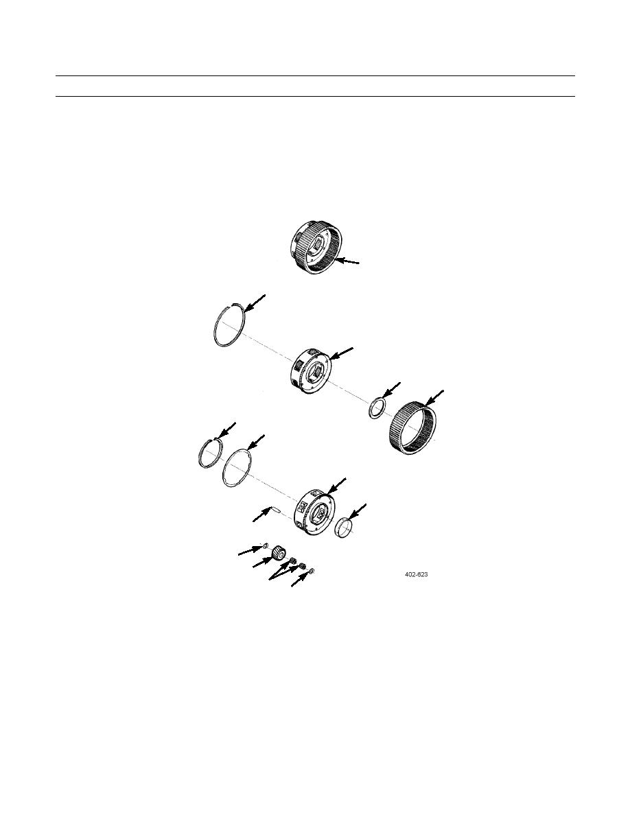
P1 Planetary Module Disassembly - Continued |
|
||
| ||||||||||
|
|
 TM 9-2320-303-24-2
TRANSMISSION OVERHAUL - CONTINUED
0248 00
MODULE OVERHAUL - CONTINUED
P1 Planetary Module Disassembly - Continued
8.
Inspect and measure bushing (6) inside P1 planetary carrier (3) for wear or damage. Maximum ID allowed is 3.516 in
(89.32 mm). If bushing is worn, remove and replace.
9.
Check spline wear of P1 planetary carrier (3) and P2 planetary ring gear (5). Maximum allowed spline wear is 3.015 in
(0.38 mm).
2
1
3
4
5
13
12
3
6
11
10
9
8
7
P1 Planetary Module Assembly
1.
If removed, install bushing (6) into P1 planetary carrier (3) using a press and tool (J37038). Press new bushing flush to
0.016 in (0.40 mm) below surface.
2.
Install two bearing assemblies (8) into center of pinion gear (9). Install thrust washers (7 and 10) inside P1 planetary car-
rier (3), align thrust washer tangs with slots in planetary, and retain them with petrolatum. Slide pinion gear and bearing
assemblies into side of P1 planetary carrier between thrust washers. Repeat procedure for remaining five pinion gears.
3.
Install six spindles (11) so that lower step is positioned for proper installation of indexing ring (12).
4.
0248 00-33
|
|
Privacy Statement - Press Release - Copyright Information. - Contact Us |
