 |
|||
|
|
|||
|
Page Title:
Front Support and Charging Oil Pump Module Assembly - Continued |
|
||
| ||||||||||
|
|
 TM 9-2320-303-24-2
TRANSMISSION OVERHAUL - CONTINUED
0248 00
MODULE OVERHAUL - CONTINUED
Front Support and Charging Oil Pump Module Assembly - Continued
9.
Secure pump housing (1) to front support (3) with eight bolts (5). Tighten bolts to 38-45 lb-ft. (51-61 Nm).
NOTE
Butt-joint seal rings require special handling during assembly. Seal rings contain materials that absorb mois-
ture from atmosphere, causing them to expand. Check seal ring end clearance before installation to ensure
seal ring has not expanded.
10.
Measure end gap of three rotating seal rings (4) before installation. Insert seal rings into the rotating clutch hub bore of
front support (3) and measure end gap with a thickness gage. Seal ring end gap must be 0.040-0.057 in (1.00-1.44 mm).
11.
Install three rotating seal rings (4) on front support hub.
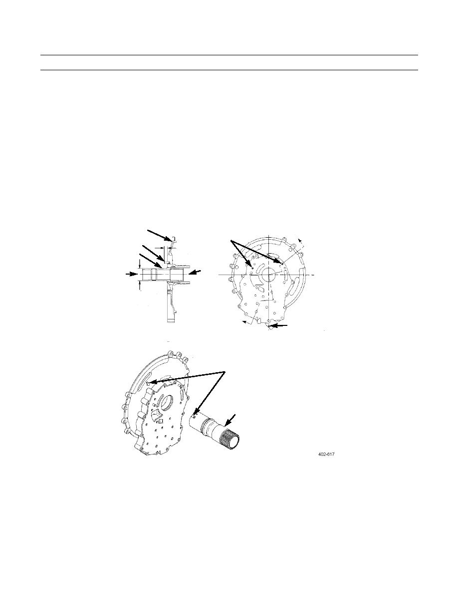
FRONT SUPPORT
DOWEL
E
PINS
DOWEL PIN
14.5 mm
ROUND SLEEVE
(0.57 in)
REMOVE
INSTALL
SPLINE OD T.I.R.
0.13 mm
(0.005 in)
E
RELIEF VALVE
SECTION E-E
BORE
BOTTOM
VIEW A
VIEW B
TO INSTALL, ALIGN FLAT ON
GROUND SLEEVE WITH ARROW
ON FRONT SUPPORT
GROUND SLEEVE
VIEW C
0248 00-21
|
|
Privacy Statement - Press Release - Copyright Information. - Contact Us |
