 |
|||
|
|
|||
|
Page Title:
Front Support and Charging Oil Pump Module Disassembly - Continued |
|
||
| ||||||||||
|
|
 TM 9-2320-303-24-2
TRANSMISSION OVERHAUL - CONTINUED
0248 00
MODULE OVERHAUL - CONTINUED
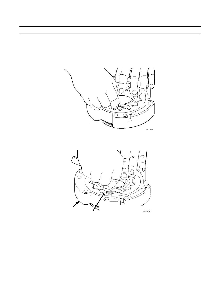
Front Support and Charging Oil Pump Module Disassembly - Continued
7.
Measure gear tooth tip clearance. Maximum allowable clearance is 0.006 in (0.15 mm).
MAX GEAR
TOOTH TIP
CLEARANCE
0.15 mm (0.006 in)
8.
Measure driven gear to pump housing clearance. Maximum allowable clearance is 0.012 in (0.30 mm).
MAX CLEARANCE BETWEEN
PUMP HOUSING
DRIVEN GEAR OD AND
DRIVEN GEAR
PUMP HOUSING
0.30 mm (0.012 in)
9.
Inspect and measure bushing (6) inside inner gear of gear set (2). The maximum ID of bushing is 2.635 in (66.93 mm).
If bushing is damaged or out of tolerance, remove.
10.
Remove 14 bolts (16) securing wear plate (15) to front support (3). Remove wear plate.
11.
Inspect roller bearing (14). If damaged, remove using drift and hammer.
12.
Inspect and measure front support sleeve (9). Minimum OD diameter of front support sleeve is 4.717 in (119.81 mm). If
sleeve is damaged or out of tolerance, remove.
13.
Inspect front support dowel pins (8 and 13). If damaged, remove.
0248 00-19
|
|
Privacy Statement - Press Release - Copyright Information. - Contact Us |
