 |
|||
|
|
|||
|
Page Title:
Removal of P2 Planetary Module, C5 Clutch Pack, and P1 Planetary Module |
|
||
| ||||||||||
|
|
 TM 9-2320-303-24-2
TRANSMISSION OVERHAUL - CONTINUED
0248 00
DISASSEMBLY - CONTINUED
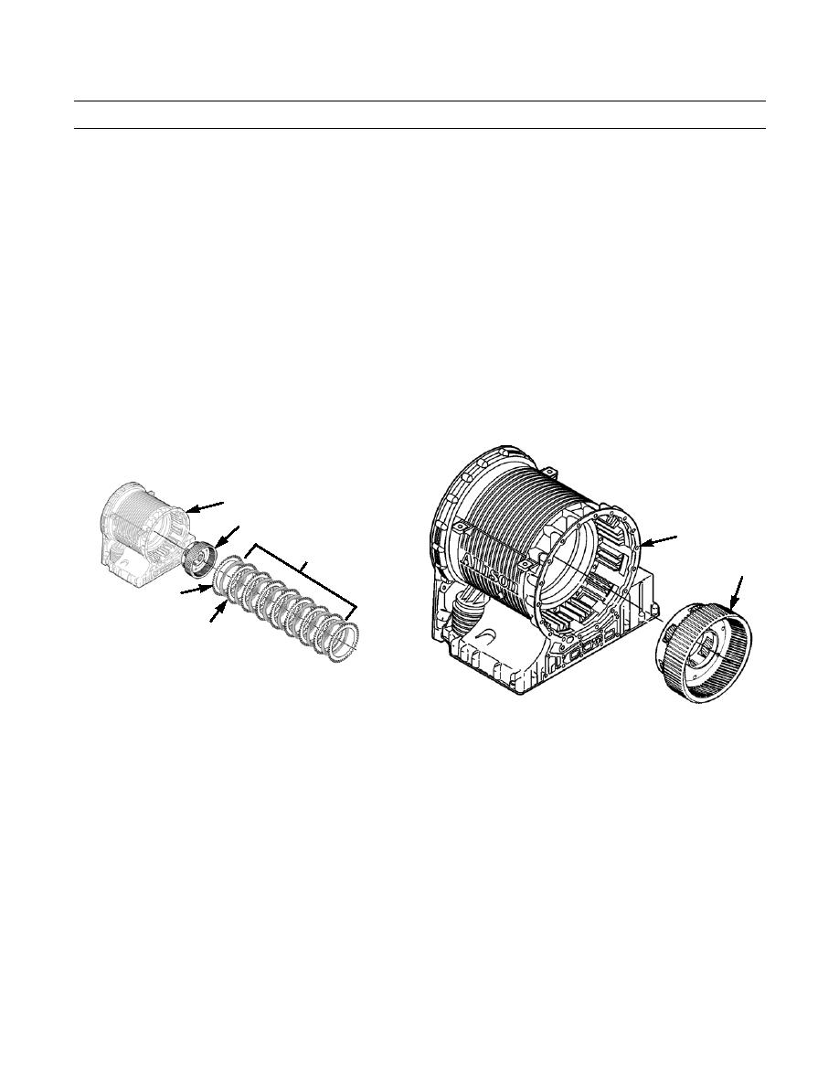
Removal of P2 Planetary Module, C5 Clutch Pack, and P1 Planetary Module
1.
Lift P2 planetary module (41) from main housing (24).
2.
Lift C5 clutch pack (42), containing eight friction plates (43) and nine steel reaction plates (44), from main housing (24).
3.
Measure, tag, and note thickness and cone of each friction plate (43). Minimum thickness is 0.137 in (3.48 mm). Maxi-
mum allowable cone is 0.010 in (0.25 mm).
4.
Measure, tag, and note thickness and cone of each steel reaction plate (44). Minimum thickness is 0.095 in (2.41 mm).
Maximum allowable cone is 0.010 in (0.25 mm).
5.
Lift P1 planetary module (45) from main housing (24).
24
41
24
42
45
43
44
402-601
402-602
Removal of Front Support and Charging Pump Module and Rotating Clutch Module
NOTE
Note size and position of 14 bolts securing front support and charging pump module to main housing, to aid
during assembly.
1.
Remove seven bolts (48) and seven bolts (46) securing front support and charging pump module (47) to main housing
(24).
2.
Lift front support and charging pump module (47) from main housing (24).
3.
Install an M16 lifting eye bolt into turbine shaft (49). Attach a suitable hoist to lifting eye.
4.
Using hoist, remove turbine shaft (49) and rotating clutch module (50) from main housing (24).
0248 00-8
|
|
Privacy Statement - Press Release - Copyright Information. - Contact Us |
