 |
|||
|
|
|||
|
Page Title:
Figure E2. VIM Components Location and Pin-Out Diagram |
|
||
| ||||||||||
|
|
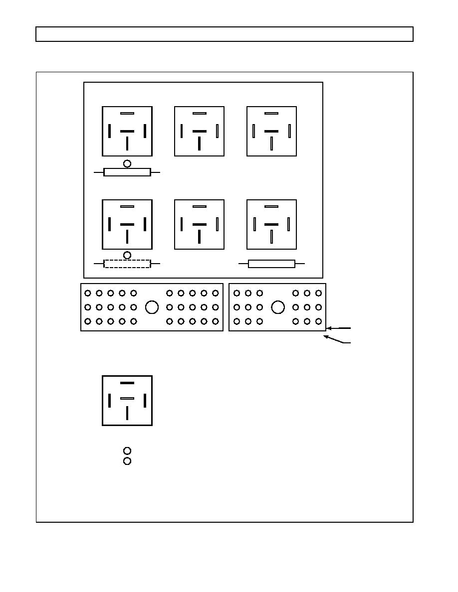 WTEC III ELECTRONIC CONTROLS TROUBLESHOOTING MANUAL
APPENDIX E -- WELDING ON VEHICLE/VEHICLE INTERFACE MODULE
(K4)
(K5)
(K6)
WIRE 114/SFO 1
WIRE 125/SFO 4
WIRE 112/SFO 3
A3/30
F3/30
R3/18
C1/30
P2/18
K1 & 2/30
C1/30
N2/18
B2/30
C2/30
D1/30
R1/18
R1/18
A2/30
F2/30
E1/30
2
F1/18
C1/30
IGNITION FUSE
(K1)
(K2)
(K3)
WIRE 113/REVERSE WARNING
WIRE 132/SFO 2
WIRE 123/NEUTRAL START
A1/30
E3/30
F1/30
M1/18
C1/30
L1 & 2/18
P1/18
R2/18
C1/30
D2/30
()
(+)
R1/18
R1/18
K1 & 2/30
E2/30
G1/30
B1/30
1
C1/30
F1/18
J1 & 2/30
Q1 & 2/18
IGNITION FUSE
MAIN FUSE
1
1
2
2
3
3
L
M
N
P
Q
R
TERMINAL BOARD
IDENTIFICATION
A
B
C
D
E
F
G
H
J
K
A
B
C
D
E
F
HARNESS
30-WAY CONNECTOR
18-WAY CONNECTOR
CONNECTOR
(PIN ID/18)
(PIN ID/30)
IDENTIFICATION
See page D-26 for
See page D-25 for
wire/terminal usage.
wire/terminal usage.
87
86
85
87A
30
Pin numbering on
bottom of relay
Ignition fuse position in early VIM
1
Ignition fuse must be in place and not open for there to be
2
continuity between pins C1/30 and R1/18
V03425
0021 00168
|
|
Privacy Statement - Press Release - Copyright Information. - Contact Us |
