 |
|||
|
|
|||
|
Page Title:
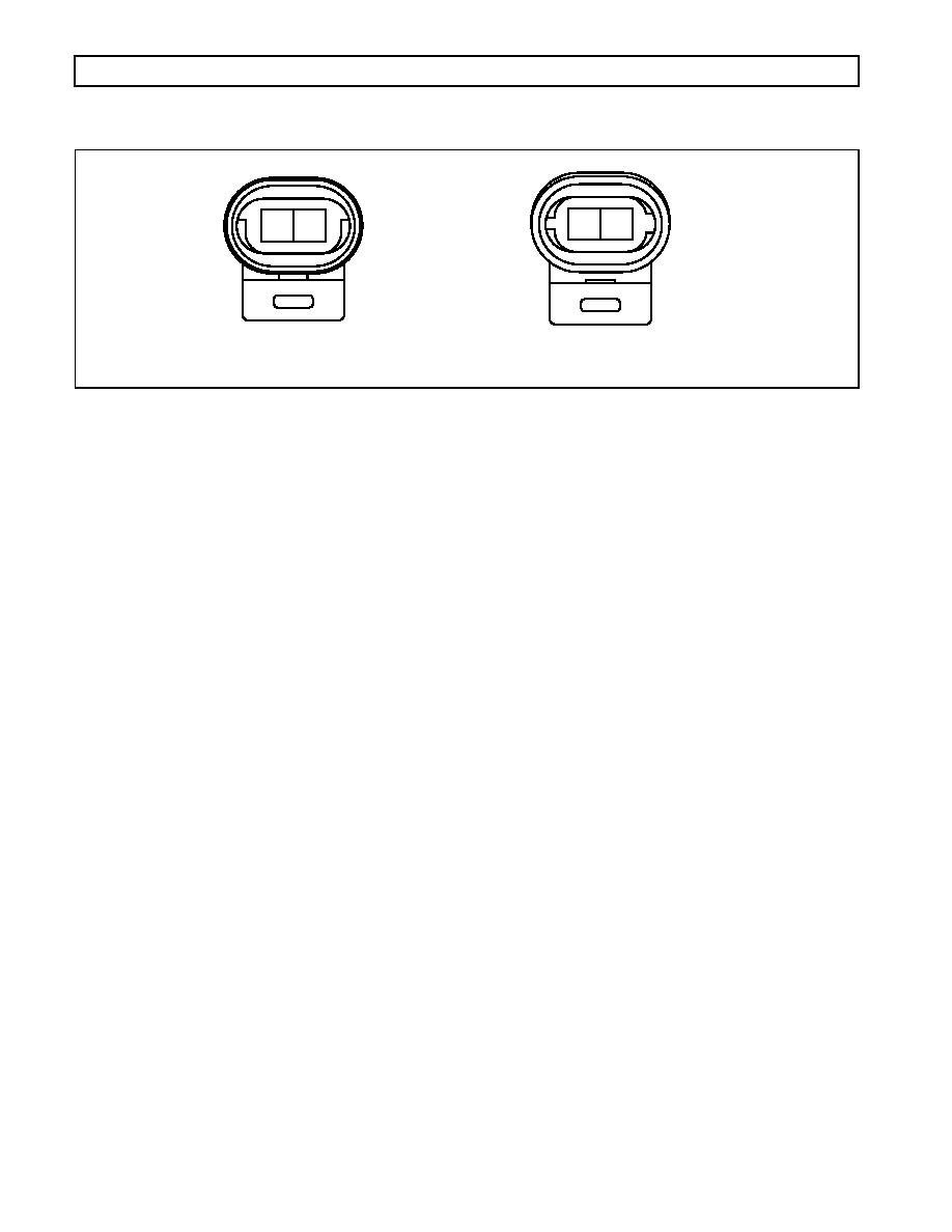
Figure D8. Speed Sensor Connector |
|
||
| ||||||||||
|
|
 WTEC III ELECTRONIC CONTROLS TROUBLESHOOTING MANUAL
APPENDIX D -- WIRE/CONNECTOR CHART
A
B
A
B
SPEED SENSOR
ACCUMULATOR (N SOLENOID)
V04850
Figure D8. Speed Sensor Connector
ENGINE SPEED SENSOR CONNECTOR
Terminal No.
Color
Wire No.
Description
Termination Point(s)
A
Tan
141-T14
Engine Speed Sensor Hi
ECU-T14
B
Orange
150-T30
Engine Speed Sensor Lo
ECU-T30
TURBINE SPEED SENSOR CONNECTOR (HD/B 500 ONLY)
Terminal No.
Color
Wire No.
Description
Termination Point(s)
A
Orange
149-T15
Turbine Speed Sensor Hi
ECU-T15
B
Blue
140-T31
Turbine Speed Sensor Lo
ECU-T31
OUTPUT SPEED SENSOR CONNECTOR
Terminal No.
Color
Wire No.
Description
Termination Point(s)
A
Yellow
139-T16
Output Speed Sensor Hi
ECU-T16
B
Green
148-T32
Output Speed Sensor Lo
ECU-T32
ACCUMULATOR (N) SOLENOID
Terminal No.
Color
Wire No.
Description
Termination Point(s)
A
Blue
101-T24
N Solenoid Lo
ECU-T24
B
Yellow
116-T19
N Solenoid Hi
ECU-T19
MD RETARDER (H SOLENOID, TID 2)
Terminal No.
Color
Wire No.
Description
Termination Point(s)
A
White
127-T23
H Solenoid Lo
ECU-T23
B
Yellow
116C-T19
H Solenoid Hi
ECU-T19
0021 00150
|
|
Privacy Statement - Press Release - Copyright Information. - Contact Us |
