 |
|||
|
|
|||
|
Page Title:
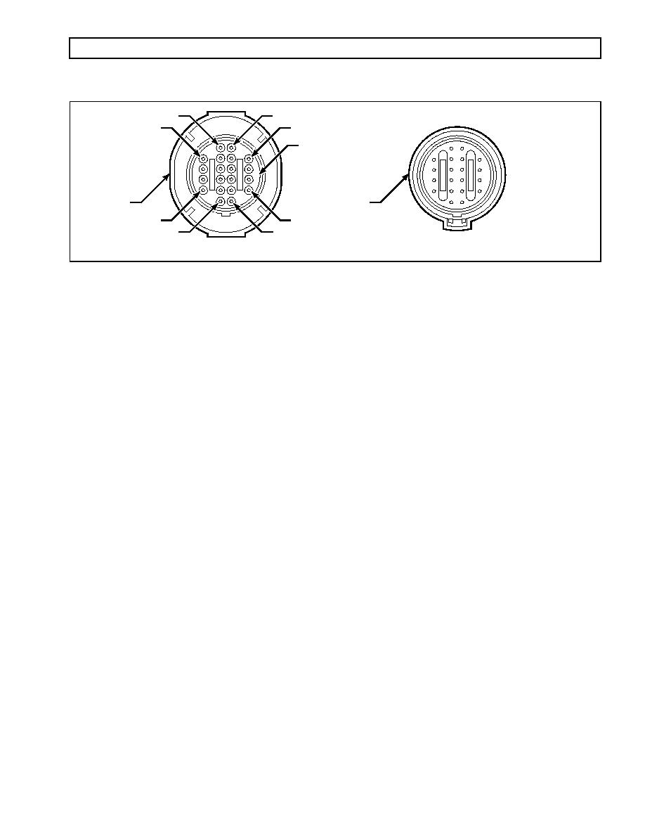
Figure D6. Remote Selector Connector |
|
||
| ||||||||||
|
|
 WTEC III ELECTRONIC CONTROLS TROUBLESHOOTING MANUAL
APPENDIX D -- WIRE/CONNECTOR CHART
S
K
W
D
COLOR CODE GREEN
HARNESS
DEVICE
T
A
L
E
NOTE: Letters I, O, and Q not used
V03369
Figure D6. Remote Selector Connector
REMOTE SHIFT SELECTOR CONNECTOR -- PRIMARY SELECTOR
Terminal No.* Color Wire No.
Description
Termination Point(s)*
A
Orange
170-S5
Primary Shift Selector, Data Bit 1
ECU, S5
B
Green
171-S6
Primary Shift Selector, Data Bit 2
ECU, S6
C
Blue
172-S7
Primary Shift Selector, Data Bit 4
ECU, S7
D
Yellow
173-S8
Primary Shift Selector, Data Bit 8
ECU, S8
E
Tan
174-S9
Primary Shift Selector, Parity
ECU, S9
F
G
H
J
K
L
Orange
176-S15
General Purpose Output 6
VIWS-L, SSS-L
M
Green
175-S10
Shift Selector Mode Output
SSS-M
N
Pink
124-S3
Sensor Power
RMR-C, SSS-N
P
Gray
143-S32
Battery Ground
VIWS-P, SSS-P, DDRP-A, DDRD-E,
or OBDII-5
R
Pink
136-S16
Battery Power
SSS-R
S
Blue
180-S14
Shift Selector Display
SSS-S
T
White
186
Dimmer Input A
SSS-T
U
Yellow
187
Dimmer Input B
SSS-U
V
Gray
188
Dimmer Ground
SSS-V
W
* Terminal number and termination points shown only apply when an Allison Transmission recommended harness configuration and bulk-
head connector are used.
0021 00147
|
|
Privacy Statement - Press Release - Copyright Information. - Contact Us |
