 |
|||
|
|
|||
|
Page Title:
APPENDIX B -- CHECKING CLUTCH AND RETARDER PRESSURES |
|
||
| ||||||||||
|
|
 W T E CWI IECEII E LECTO NNCC CONTROLS S RT R OLESL E S HINO T I ANUALA N U A L
T I I L EC T R RO I I C O N T R O L T OUB U B HOOT O G MN G M
Checking individual clutch pressures helps to determine if a transmission malfunction is due to a mechanical or an
electrical problem. Properly making these pressure checks requires transmission and vehicle (or test stand)
preparation, recording of data, and comparing recorded data against specifications provided. These instructions are
for all WT Series transmissions.
NOTE:
Check to see if there are diagnostic codes set which are related to the transmission difficulty you are
evaluating. Proceed to make mechanical preparations for checking clutch pressures after codes have
first been evaluated.
A.
Transmission and Vehicle Preparation
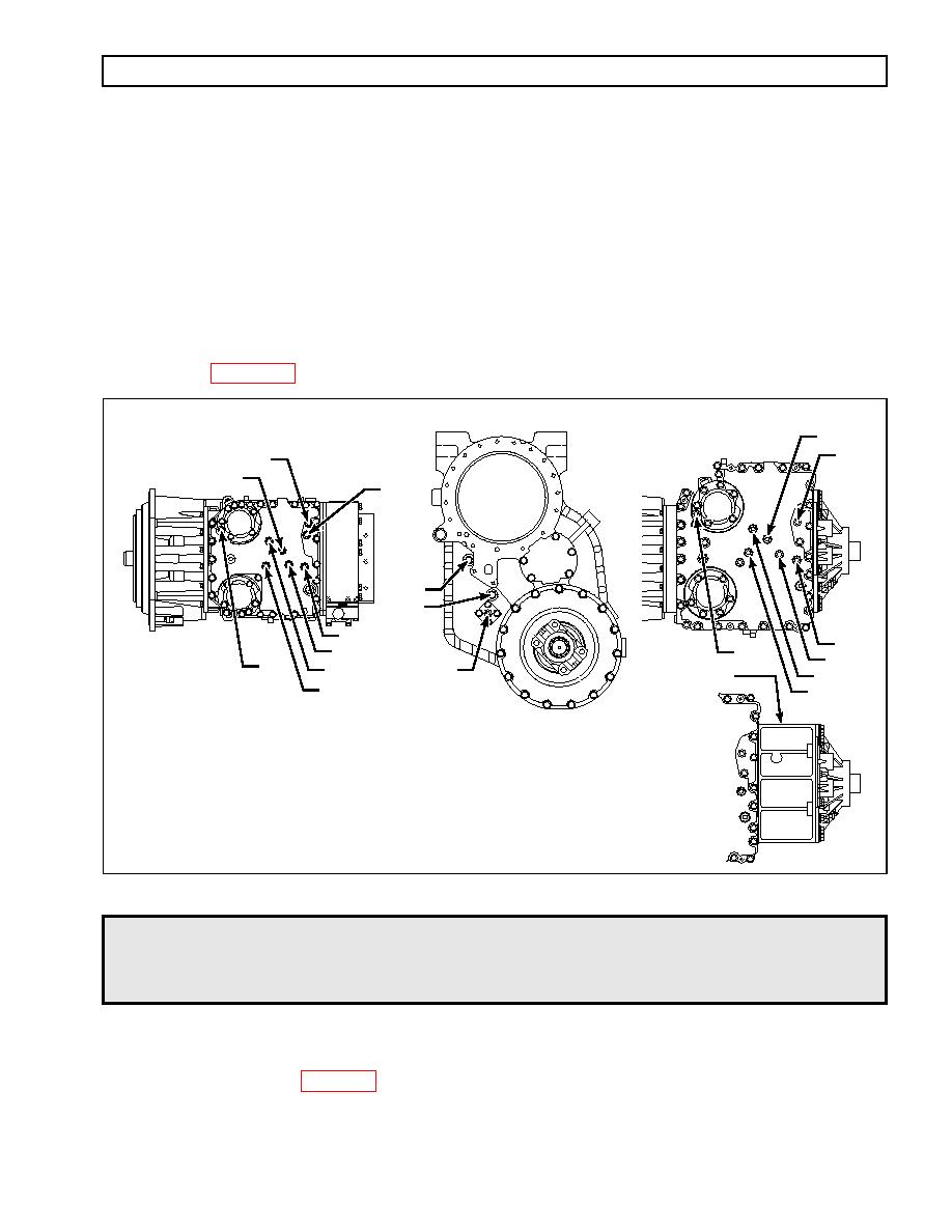
1. Remove the plugs from the pressure tap locations where measurement is desired (refer to
MD/B 300/B 400
MD 3070PT TRANSFER CASE
HD/B 500
C3
C5
C6 (MD 3070PT ONLY)
C3
C5
MAIN
C7
MAIN
MAIN
C2
LU
C2
LU
C4
T-CASE
C4
C6 PRESSURE TAP
CONNECTOR
(On left side of
C1
C1
adapter housing,
HD 4070
near the bottom)
FRONT VIEW
NOTE: Retarder charging pressure tap is located on the
retarder control valve body for all models with retarder.
V05929
Be sure that the hydraulic fittings have the same thread as the plugs removed
CAUTION:
(7/16-20 UNF-2A). Also please note that these fittings must be straight thread,
O-ring style. Failure to do this will result in damage to the control module.
2. Install hydraulic fittings suitable for attaching pressure gauges or transducers.
3. Connect pressure gauges or transducers. Pressure gauge set J 26417-A is available for this
purpose. See Table B2 for pressure levels expected.
4. Check that engine speed can be monitored (Pro-Link 9000 diagnostic tool may be used for this
purpose).
|
|
Privacy Statement - Press Release - Copyright Information. - Contact Us |
