 |
|||
|
|
|||
|
Page Title:
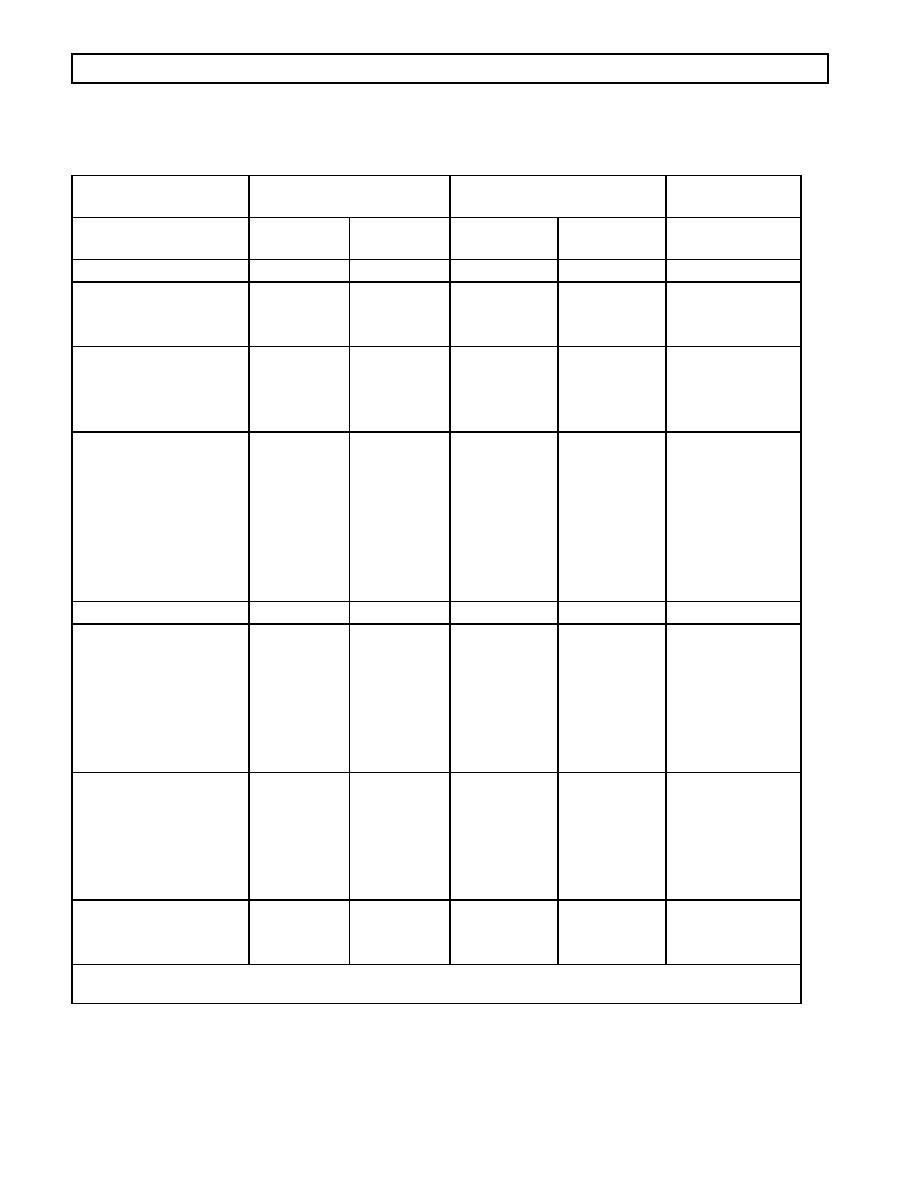
Table 51. RMR Device Resistance Checks |
|
||
| ||||||||||
|
|
 WTEC III ELECTRONIC CONTROLS TROUBLESHOOTING MANUAL
CODE 64 XX -- RETARDER MODULATION REQUEST DEVICE FAULT
Table 51. RMR Device Resistance Checks
Resistance Check in
Wiring to Control
Voltage Signal **
Resistance Module*
Device
Resistance
% Retarder
Voltage
5%
Application
0.2 v
Description
Terminals
Device Terminal
Auto Full On
A to C
12K
100
3.6
No connections
Pressure Switch
A to C
32K
0
1.1
A
Full On
100
3.6
B
High
3-Step E-10R Bendix
A to C
32K
0
1.1
A
Pedal
32
1.9
B
58
2.8
C
100
3.6
D
6-Step Hand Lever --
A to C
32K
Off
0
1.1
+
Position 1
14
1.5
1
Position 2 Position
28
1.9
2
3 Position 4
45
2.3
3
Position 5 Position
65
2.8
4
6
82
3.2
5
100
3.6
6
Auto 1/2 On
A to C
12K
50
2.4
No connections
3 Pressure Switches --
A to C
32K
0
1.1
Low
32
1.9
A
B
Medium
68
2.8
A
B
High
100
3.6
A
B
Auto 1/3 On
A to C
21.4K
2 Pressure Switches
Auto
32
1.9
A
Medium
68
2.8
B
High
100
3.6
A
B
Dedicated Pedal
No Checks
Interface not
0
0.7 1.2
A
a resistance
100
3.4 3.5
B
module
C
* Resistance module must be disconnected from the wiring harness and retarder control devices
** These voltages must be measured between terminals A and B.
0021 00116
|
|
Privacy Statement - Press Release - Copyright Information. - Contact Us |
