 |
|||
|
|
|||
|
Page Title:
CODE 42 XX -- SHORT-TO-BATTERY IN SOLENOID CIRCUIT |
|
||
| ||||||||||
|
|
 WTEC III ELECTRONIC CONTROLS TROUBLESHOOTING MANUAL
Main code 42 indicates the ECU has detected a short-to-battery condition in a solenoid wiring circuit. The DO
NOT SHIFT response is activated when some subcodes are detected, all solenoids are turned off and the CHECK
TRANS light is illuminated. All solenoids have a driver on the low (ground) side which can turn off the solenoid.
All solenoids also have a driver on the high (power) side of the solenoid. Even though the high side driver can be
turned off, a short-to-battery means the solenoid is continuously powered at an unregulated 12V or 24V instead of
a regulated (pulse width modulated) voltage. The low side driver will not tolerate direct battery current and will
open, causing the solenoid to be deenergized.
NOTE:
For subcodes 12, 13, 14, 15, 16, 22 -- neutral start is inoperable; all display segments are on if the
code is logged during ECU initialization (ignition on). Subcodes 21, 23, 24, and 26 will not trigger the
CHECK TRANS light.
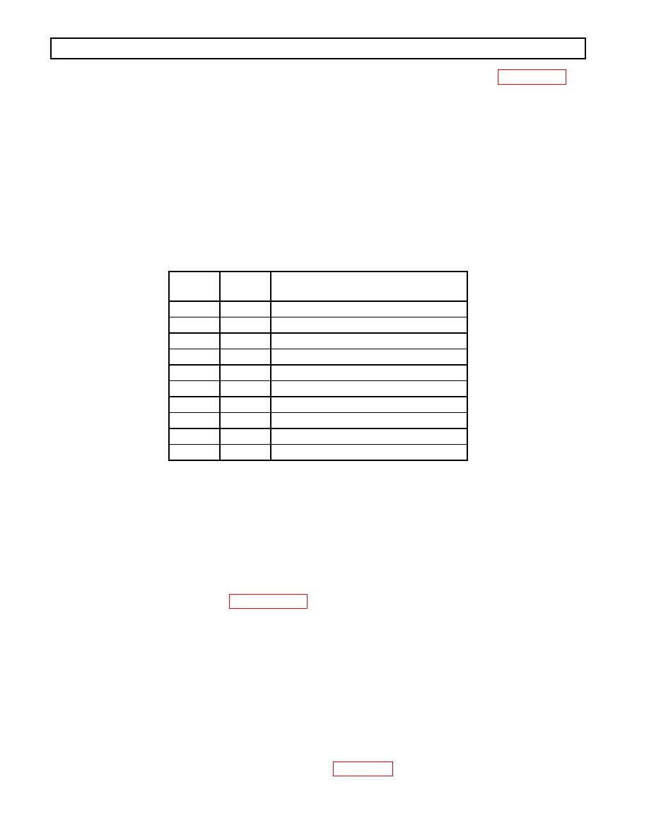
Main
Code
Subcode
Meaning
42
12
Short-to-battery A Solenoid Circuit
42
13
Short-to-battery B Solenoid Circuit
42
14
Short-to-battery C Solenoid Circuit
42
15
Short-to-battery D Solenoid Circuit
42
16
Short-to-battery E Solenoid Circuit
42
21
Short-to-battery F Solenoid Circuit
42
22
Short-to-battery G Solenoid Circuit
42
23
Short-to-battery H Solenoid Circuit
42
24
Short-to-battery J Solenoid Circuit
42
26
Short-to-battery N Solenoid Circuit
A.
Active Indicator Clearing Procedure:
Power down
Manual
NOTE:
Intermittent connections or lack of battery-direct power and ground connections may cause this and
other codes.
NOTE:
Before troubleshooting, read Paragraph 56. Also, check battery and ECU input voltages.
NOTE:
Energizing the solenoids and listening for ball/plunger movement is sometimes useful in
troubleshooting.
NOTE:
"N" solenoid on the retarder accumulator has either a 12.5 1.5 Ohm coil or a 23.5 2.4 Ohm coil
and is not correlated to sump temperature.
PROBING THE CONNECTOR
When testing the control system from the feedthrough connector with the internal harness connected, the resistance
of each solenoid can be measured by using a VOM. Refer to Figure 515 for solenoid resistance versus
temperature.
0021 0084
|
|
Privacy Statement - Press Release - Copyright Information. - Contact Us |
