 |
|||
|
|
|||
|
|
|||
| ||||||||||
|
|
 WTEC III ELECTRONIC CONTROLS TROUBLESHOOTING MANUAL
D SUMP STIC CODES
Main code 24 indicates the ECU has detected either a high or low fluid temperature in the transmission sump (via
the sump temperature sensor in the internal harness). All shifts are inhibited when code 24 12 is set (only Neutral
range operation is allowed). No upshifts are allowed above a calibration range when code 24 23 is set. All inhibits
are cleared when the temperature conditions are normal. A related code is 33 12 which indicates a temperature
reading outside the usable range of the sensor and indicates a probable sensor failure.
NOTE:
When an ECU with a version 8 calibration (CIN=0A...) is used with a TransID 2 transmission,
24 XX codes are set because the ECU does not have the proper calibrations for the TID 2 thermistors.
The ECU calibration must be updated to version 8A or later (CIN=0B).
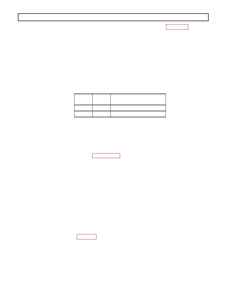
Main
Code
Subcode
Meaning
24
12
Sump fluid temperature cold
24
23
Sump fluid temperature hot
A.
Active Indicator Clearing Procedure:
Power down
Manual
Self-clearing
NOTE:
Before troubleshooting, read Paragraph 56. Also, check the ECU input voltage.
B.
Troubleshooting:
Code 24 12:
1. If the outside temperature is between 32C (26F) and 7C (+19F), the ECU will allow re-
verse, neutral, and second-range start operation. Only hold override upshifts are allowed. (See
Table 64 on next page.) The sump must be warmed to an acceptable temperature to avoid logging
codes and transmission diagnostic response.
NOTE:
Code 24 12 can result when the +5V line (wire 124) which powers the sump temperature sensor is
shorted to ground. Wire 124 also powers the TPS, OLS, RMR, retarder temperature sensor, and shift
selectors and is present in all three ECU connectors.
2. After allowing the temperatures to normalize, if ambient temperature does not match the sump
temperature reading (check using diagnostic tool), compare resistance versus sump fluid temper-
ature. Refer to Figure 58 for TID 1 thermistors and Appendix Q for TID 2 thermistors. If resis-
tance check is acceptable, then check the sensor wiring for opens, shorts, or shorts-to-ground.
3. If the sensor wiring is satisfactory, drain the fluid, remove the control module, and replace the
temperature sensor.
4. If the condition persists, replace the ECU. If replacing the ECU corrects the problem, reinstall
the original (bad) ECU to confirm that the problem is in the ECU. If the original ECU now
works, inspect the ECU connectors for any corrosion or damage that may cause an intermittent
condition. If the original problem recurs, reinstall the replacement ECU.
0021 0064
|
|
Privacy Statement - Press Release - Copyright Information. - Contact Us |
