 |
|||
|
|
|||
|
Page Title:
GENERAL DESCRIPTION |
|
||
| ||||||||||
|
|
 WTEC III ELECTRONIC CONTROLS TROUBLESHOOTING MANUAL
GENERAL DESCRIPTION
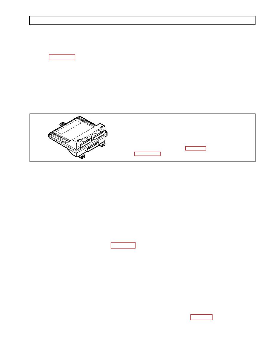
The ECU (Figure 13) contains the microcomputer which is the brain of the control system. The ECU receives and
processes information defining: shift selector position, throttle position, sump/retarder temperature, engine speed,
turbine speed, and transmission output speed. The ECU uses the information to control transmission solenoids and
valves, supply system status, and provide diagnostic information.
Each ECU has a date code stamped on the label which is attached to the outer case of the ECU. This is the date
when the ECU passed final test. This date is commonly used to denote the change configuration level of the ECU.
It is normal for the ECU date displayed electronically to be a few days prior to the date shown on the label.
NOTE: ECU wiring harness connector retainers
are individually keyed and color-coded to
ensure that the proper connector is attached
to the correct ECU socket. The color of the
UE
connector retainer should match the color of
BL
the connector strain relief (see Appendix E,
ECU
UE
BL
V03352.01
SHIFT SELECTOR
Pushbutton and lever shift selectors for the WTEC III Series are remote mounted from the ECU and connected to
the ECU by a wiring harness. Both of these shift selectors have a single digit LED display and a mode indicator
(LED). During normal transmission operation, illumination of the LED indicator shows that a secondary or special
operating condition has been selected by pressing the MODE button. During diagnostic display mode, illumination
of the LED indicator shows that the displayed diagnostic code is active. Display brightness is regulated by the same
vehicle potentiometer that controls dash light display brightness. More information on both types of shift selectors
is continued below.
A.
There is a full-function pushbutton shift selector and a strip pushbutton shift selector. Strip
pushbutton shift selectors are used by European OEMs. A full-function shift selector has a MODE
button and diagnostic display capability through the single digit LED display. The strip pushbutton
shift selector does not have a MODE button, diagnostic capability, or adjustable illumination. The
full-function pushbutton shift selector has six (6) pushbuttons which are R (Reverse), N (Neutral),
D (Drive), ⇓ (Down), ⇑ (Up), and MODE. Manual forward range downshifts and upshifts are made
by pressing the ⇓ (Down) or ⇑ (Up) arrow buttons after selecting D (Drive). The N (Neutral) button
has a raised lip to aid in finding it by touch. The MODE button is pressed to select a secondary or
special operating condition, such as ECONOMY shift schedule. Diagnostic information is obtained
by pressing the ⇑ (Up) and ⇓ (Down) arrow buttons at the same time. The strip pushbutton shift
selector has either three or six range selection positions as shown in Figure 14. When a strip
pushbutton shift selector is used, diagnostic information must be obtained by using the
Pro-Link 9000 or a customer-furnished remote display.
|
|
Privacy Statement - Press Release - Copyright Information. - Contact Us |
