 |
|||
|
|
|||
|
Page Title:
DIAGNOSTIC AND TESTING PROCEDURE - CONTINUED |
|
||
| ||||||||||
|
|
 TM 9-2320-303-24-1
ANTI-LOCK BRAKE SYSTEM TROUBLESHOOTING AND TESTING - CONTINUED
0019 00
DIAGNOSTIC AND TESTING PROCEDURE - CONTINUED
4.
Turn the ignition to the ON/RUN position. The Pro-Link screen should power up.If the Pro-Link does not power up, or
if the screen indicates NO DATA RECEIVED:
Check connections.
Make sure the cartridge is properly connected to the Pro-Link keypad.
Verify 12 volts DC power and ground at the connector and ABS ECU.
Check the fuse panel for a blown fuse.
Check for proper wiring in the diagnostic connector.
PRO-LINK SCREENS
This paragraph provides basic screen explanations for the Pro-Link 9000 with a Rockwell WABCO E-version cartridge.
For complete operating instructions and test information, refer to the Pro-Link manual. The most commonly used types of
screens are the Fault Information screens and the Component Test screens.
Fault Information Screens:
1.
a.
Existing Faults: Use these screens to identify existing faults. The Pro-Link screen displays a written description of
the fault, including the location on the vehicle where each exists. As long as there is an active (existing) fault in the
system, the Pro-Link will not let you clear faults.
b.
Stored Faults: Use these screens to identify faults stored in the ECU memory. Stored faults may be existing faults
that have been repaired, or faults that existed for a short time, then corrected themselves. After displaying the
stored faults, the Pro-Link lets you erase them from memory. All stored faults are cleared at one time.
Using Pro-Link:
2.
a.
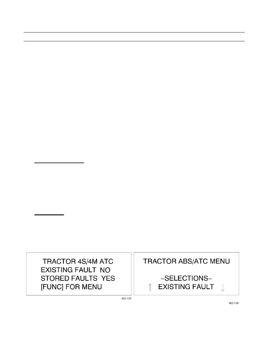
The following illustrates a typical fault screen sequence for a 4S/4M ABS system with an existing fault.
(1)
Fig 15 indicates existing and stored faults in the system. Press FUNC to display the menu shown in Fig 16.
Fig 15. Pro-Link Screen One
Fig 16. Pro-link Screen Two
0019 00-17
|
|
Privacy Statement - Press Release - Copyright Information. - Contact Us |