 |
|||
|
|
|||
|
Page Title:
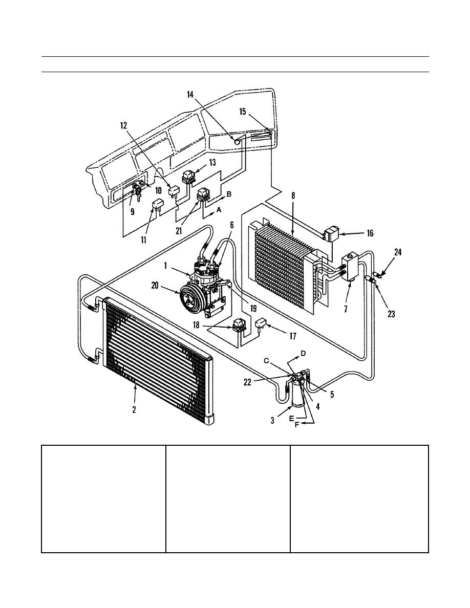
Figure 1. Air Conditioning System Components. |
|
||
| ||||||||||
|
|
 TM 9-2320-303-24-1
AIR CONDITIONING SYSTEM TROUBLESHOOTING AND TESTING - CONTINUED
0018 00
Figure 1. Air Conditioning System Components.
A.
To resistor block
D.
To engine fan thermal switch
B.
To blower motor
E.
From A/C clutch relay
C.
From engine fan thermal switch
F.
To compressor clutch
17.
Circuit Breaker (15A)
9.
Ignition Switch
1.
Compressor
18.
A/C Clutch Relay
10.
Start Button
2.
Condensor
19.
11.
Circuit Breaker (10A)
3.
Receiver-drier
20.
Compressor Clutch
12.
Circuit Breaker (30A)
4.
Binary Switch
21.
High-Speed Relay
13.
Power Relay
5.
Moisture Indicator
22.
Fan Cycling Switch
14.
Blower Switch
6.
High Pressure Relief Valve
23.
Discharger Service Valve
15.
"On-Off" Microswitch
7.
Expansion Valve
24.
Suction Service Valve
16.
Thermostatic Switch
8.
0018 00-5
|
|
Privacy Statement - Press Release - Copyright Information. - Contact Us |
