 |
|||
|
|
|||
|
|
|||
| ||||||||||
|
|
 TM 9-2320-302-20-2
SLACK ADJUSTER ADJUSTMENT - CONTINUED
0179 00
ADJUSTMENT - CONTINUED
7.
There must be at least 1/2 in (12.7 mm) of thread engagement between clevis and push rod. Push rod must not extend
through clevis more than 1/8 in (3.18 mm).
8.
If adjustment cannot be obtained, install new air brake chamber.
9.
Remove screw (14), spring (15), and pawl (16).
10.
Rotate wheel and tighten screw (13) until wheel does not rotate.
NOTE
A slight amount of drag will be felt during wheel rotation.
11.
Loosen screw (13) 1/4 turn and rotate wheel.
12.
Install pawl (16), spring (15), and screw (14). Tighten screw to 180-240 lb-in (20-27 Nm).
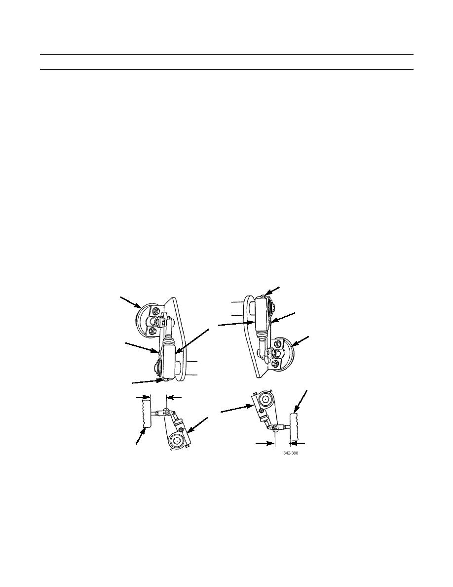
13.
Using flat tip screwdriver, pull slack adjuster (12) in direction away from brake chamber (11) while measuring total dis-
tance of travel between slack adjuster and brake chamber.
13
11
14,15,16
12
11
14,15,16
13
11
0.500-1.750 IN
12
0.500-1.750 IN
11
REAR
FRONT
14.
If total distance of travel exceeds 1-3/4 in (44.45 mm), or if total distance is not minimum of 1/2 in (12.7 mm), repeat
steps 9 through 13.
15.
Remove trestle from axle.
END OF WORK PACKAGE
0179 00-3/(-4 Blank)
|
|
Privacy Statement - Press Release - Copyright Information. - Contact Us |
