 |
|||
|
|
|||
|
|
|||
| ||||||||||
|
|
 TM 9-2320-302-20-2
FRONT BRAKE SPIDER AND BRAKE CHAMBER
BRACKET REPLACEMENT (M915A3) - CONTINUED
0175 00
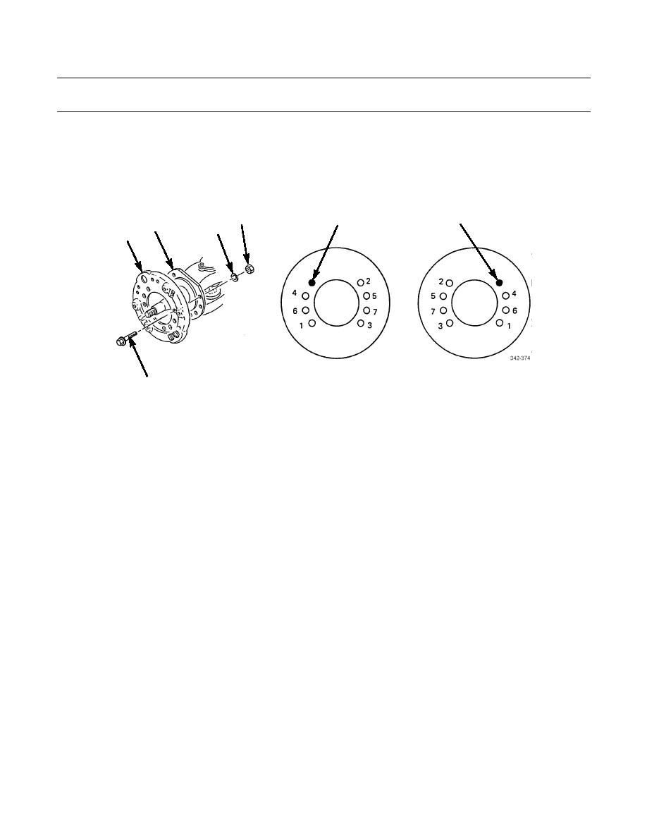
INSTALLATION
1.
Install brake spider (3) on axle flange (13) with seven screws (21), washers (12), and new locknuts (11). Tighten lock-
nuts to 75 lb-ft (102 Nm) in sequence shown. Tighten locknuts again to 150-175 lb-ft (203-237 Nm) in sequence shown.
OPEN
OPEN
FOR ABS
FOR ABS
11
SENSOR
SENSOR
13
12
3
RIGHT-FRONT SIDE
LEFT-FRONT SIDE
21
2.
Apply a light coat of lubricating oil to two bushings (5) and two new seals (4).
3.
Install two bushings (5), with label ends facing each other, on brake chamber bracket (6) to a depth of 3/8 in (9.5 mm)
from each end of brake chamber bracket.
4.
Install two new seals (4) in brake chamber bracket (6) with lip of both seals facing toward vehicle.
5.
Install brake chamber bracket (6) on brake spider (3) with two screws (2), new lockwashers (7), and nuts (8).
6.
Apply a light coat of GAA grease to two bushings (5) in brake chamber bracket (6).
7.
Install 2-piece dust shield (17) on brake spider (3) with two screws (16).
8.
Install two clamps (20), screws (19), and nuts (18) on brake spider (3).
9.
Install two new lockwashers (15) and nuts (14) on brake spider (3).
10.
Install two screws (1), new lockwashers (9), and nuts (10) on brake spider (3).
0175 00-2
|
|
Privacy Statement - Press Release - Copyright Information. - Contact Us |
