 |
|||
|
|
|||
|
Page Title:
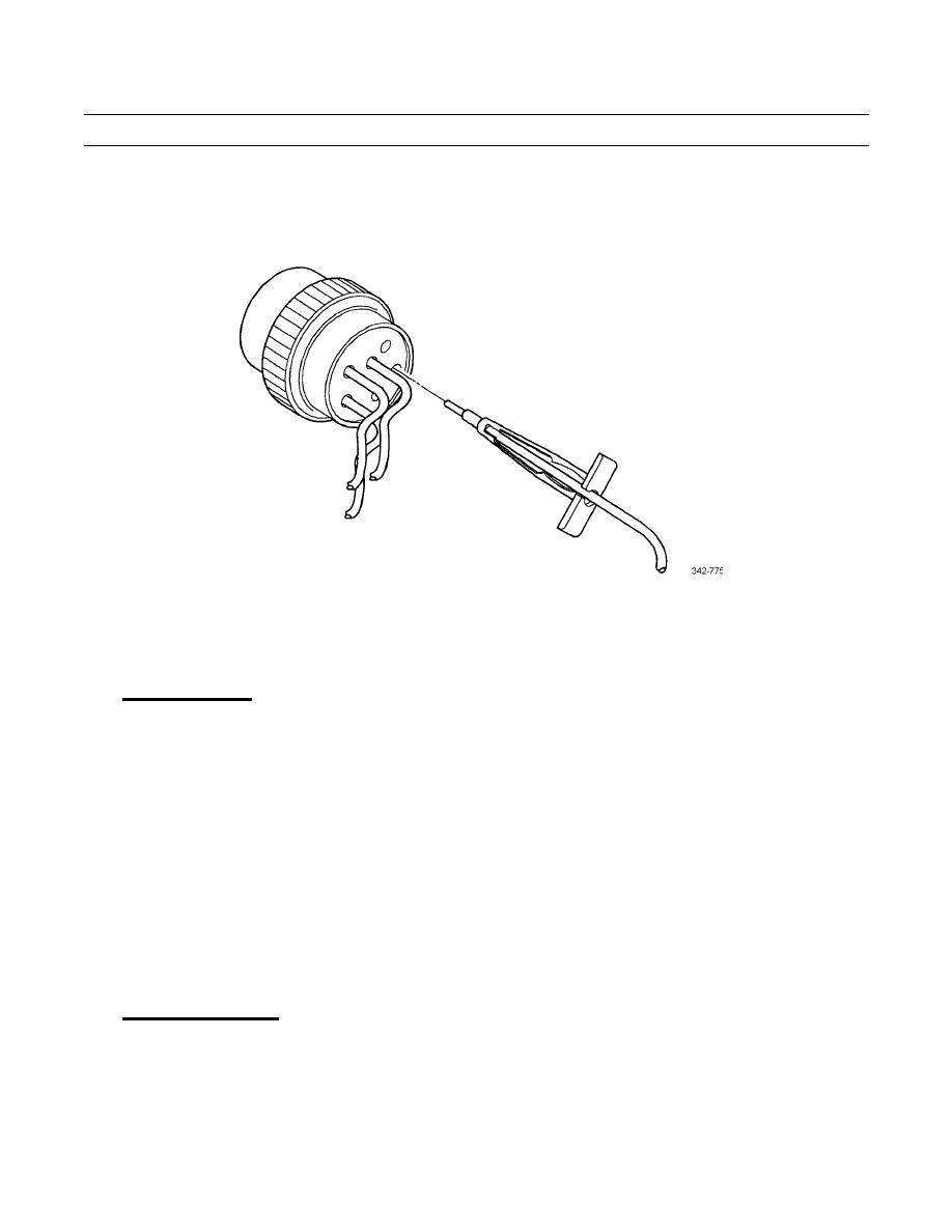
Figure 18. Removal Tool Insertion. |
|
||
| ||||||||||
|
|
 TM 9-2320-302-20-2
ELECTRICAL CONNECTORS MAINTENANCE - CONTINUED
0151 00
COMMERCIAL CONNECTOR REPAIR - CONTINUED
(2)
Slide tool along cable into insert cavity until it engages and resistance is felt. DO NOT twist or insert tool
at an angle (Figure 18).
Figure 18. Removal Tool Insertion.
(3)
Pull contact cable assembly out of connector. Keep reverse tension on cable and forward tension on tool.
SPLICING
Splicing Guidelines.
1.
a.
The following are guidelines which may be used for splices. The methods described are not the only acceptable
methods. Any method should produce a high quality, tight splice with durable insulation which can be expected to
last the life of the vehicle.
b.
The selection of crimpers and splice connectors is optional. Select a high quality crimper equivalent to Kent-
Moore tool J38706 and commercially available splice clips.
c.
The following is a list of tools required for splicing wires:
Soldering iron
Rosin core solder
Wire strippers
Heat shrink tubing
Splice clips
Crimp pliers
Splicing Straight Leads.
2.
a.
Locate broken wire.
b.
Remove insulation as required. Ensure exposed wire is clean and not corroded.
c.
Slide a sleeve of shrink wrap on wire long enough to cover splice and overlap wire insulation, about 1/4 in (6.4
mm) on both sides.
0151 00-20
|
|
Privacy Statement - Press Release - Copyright Information. - Contact Us |
