 |
|||
|
|
|||
|
|
|||
| ||||||||||
|
|
 TM 9-2320-302-20-2
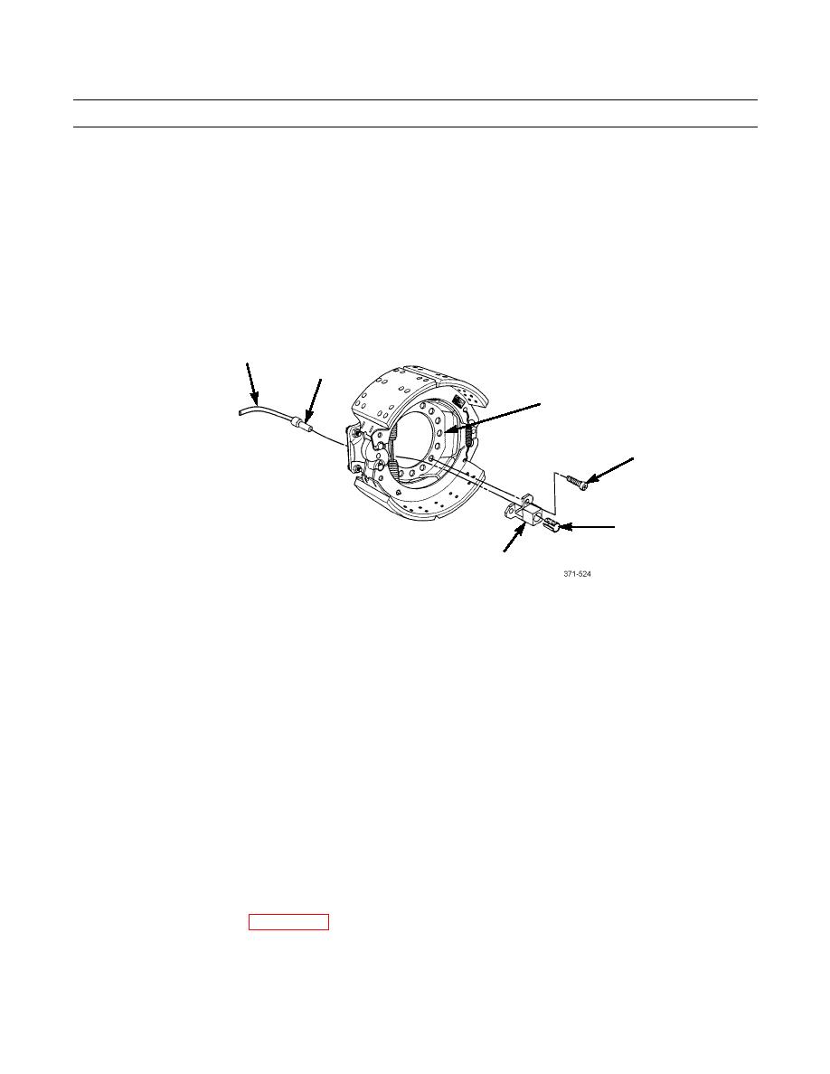
FRONT ANTI-LOCK BRAKE SYSTEM (ABS) SENSOR REPLACEMENT - CONTINUED
0122 00
REMOVAL (M916A3, M917A2)
1.
Trace ABS Sensor cable (1) to opposite end and remove all tiedown straps. Discard tiedown straps.
2.
Disconnect connector at other end of ABS sensor cable (1).
3.
Pull body of ABS sensor (2) from bracket (6) and sensor bushing (5).
4.
Remove sensor bushing (5) from bracket (6).
5.
Remove two bolts (4) and bracket (6) from brake spider (3).
1
2
3
4
5
6
INSTALLATION (M916A3, M917A2)
WARNING
Brakeshoe linings and inside drum friction surface must be free of all oil/grease and other contaminants
prior to assembly to ensure maximum braking capability. Oil/grease and other contaminants may compro-
mise braking that could lead to a serious accident resulting in injury and/or death.
1.
Position bracket (6) on brake spider (3) and install two bolts (4).
2.
Install sensor bushing (5) on bracket (6).
3.
Lightly coat outside of ABS sensor (2) with grease.
4.
Press body of ABS sensor (2) into bracket (6).
5.
Route and connect opposite end of ABS sensor cable (1).
6.
Install tiedown straps in same position as removal.
7.
Install front hub and drum (WP 0208 00).
END OF WORK PACKAGE
0122 00-4
|
|
Privacy Statement - Press Release - Copyright Information. - Contact Us |
