 |
|||
|
|
|||
|
Page Title:
SYNCHRONOUS REFERENCE SENSOR REPLACEMENT |
|
||
| ||||||||||
|
|
 TM 9-2320-302-20-2
SYNCHRONOUS REFERENCE SENSOR REPLACEMENT
THIS WORK PACKAGE COVERS
Removal, Installation
INITIAL SETUP
Tools and Special Tools
Equipment Condition
Tool kit, general mechanic's (Item 50, WP 0306 00)
Master battery switch in OFF position (TM 9-2320-
302-10)
Wrench, torque, 15-75 lb-ft (Item 57, WP 0306 00)
Coolant hose disconnected from engine block (WP
REMOVAL
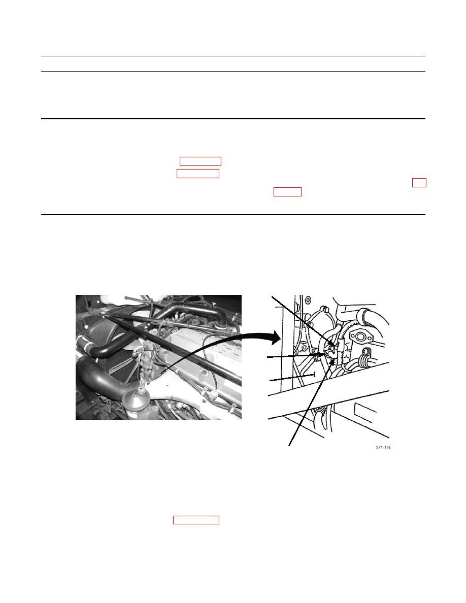
1.
On forward left side of engine, disconnect engine wiring harness connector (1) from synchronous reference sensor (2).
2.
Remove capscrew (4) and synchronous reference sensor (2) from gear housing assembly (3).
1
4
3
2
INSTALLATION
1.
Install synchronous reference sensor (2) in gear housing assembly (3) with capscrew (4). Tighten capscrew to 22-28 lb-
ft (30-38 Nm).
2.
Connect engine wiring harness connector (1) to synchronous reference sensor (2).
3.
Connect coolant hose to engine block (WP 0031 00).
END OF WORK PACKAGE
0119 00-1/(-2 Blank)
|
|
Privacy Statement - Press Release - Copyright Information. - Contact Us |
