 |
|||
|
|
|||
|
Page Title:
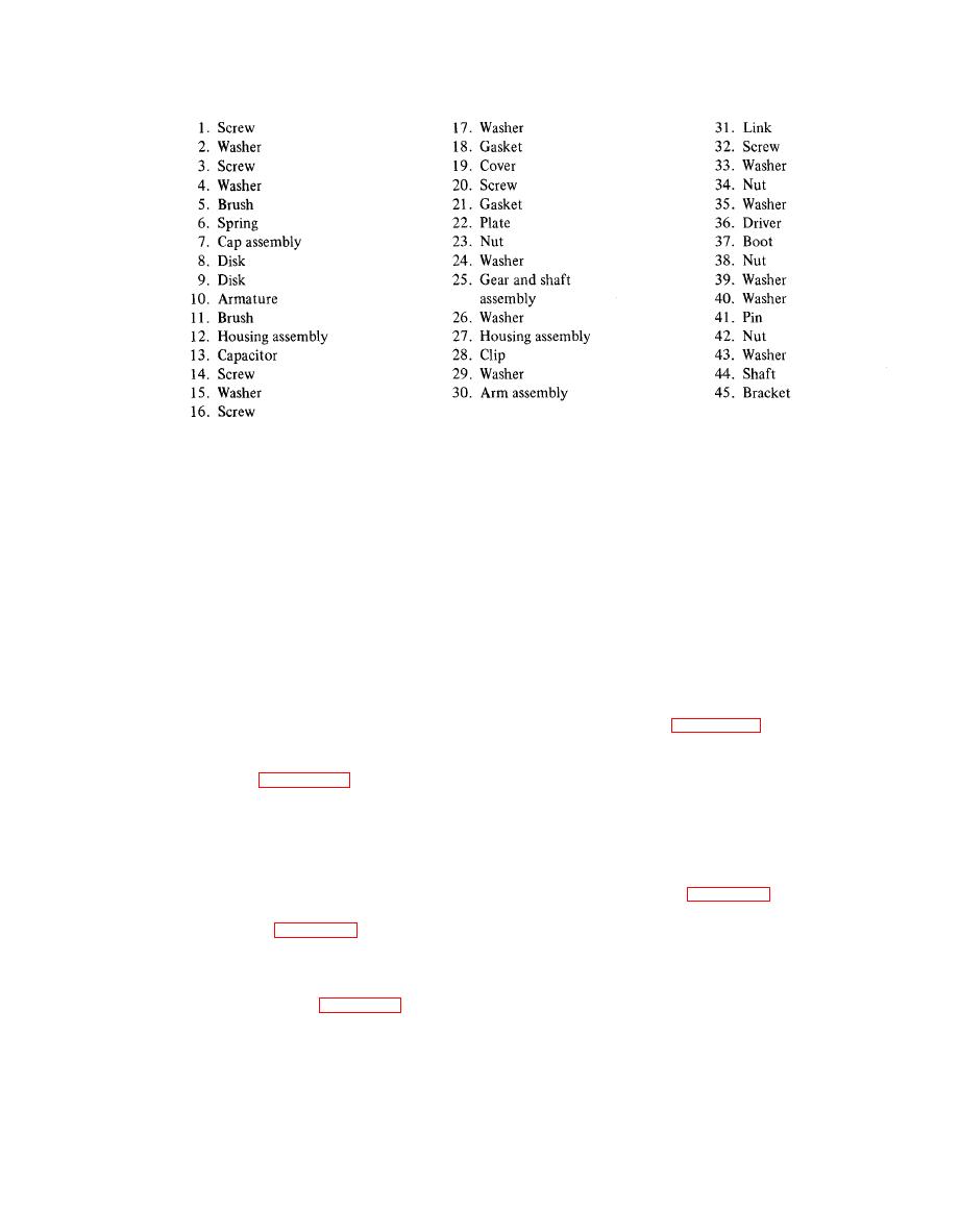
Figure 4-20. Windshield wiper (Code Cl) (Sheet 2 of 2) |
|
||
| ||||||||||
|
|
 TM 55-1740-200-14
Figure 4-20. Windshield wiper (Code Cl) (Sheet 2 of 2)
c. Remove retainer assembly (27) and remove bowl
b. Remove two cotter pins (56) and remove pin (57)
(20), spring (21), filter (22) and gasket (23) from housing
and pedal (55). Remove two screws (59), washers (60)
(24).
and nuts (61) and remove hinge plate (58).
d. Remove five screws (14) and remove body (13) and
c. Remove two screws (40), washers (41) and nuts
(42). Loosen two screws (43) and remove two levers (39)
diaphragm (15). Remove two screws (7) and remove
housing (16) and diaphragm (15) from housing (24).
and spacers (44). Remove shaft (45). Remove four screws
(47), washers (48) and nuts (49) and remove bracket
(46).
4-292. CARBURETOR.
4-288. DISASSEMBLY. None required.
4-289. FUEL PUMP.
carburetor as follows:
4-290. REMOVAL. See figure 4-28 and remove the
a. Remove air cleaner (19) and gasket (20).
fuel pump as follows:
b. Remove two nuts (25) and washers (24) and
a. Remove adapter (13), hose (14) and elbow (15).
remove carburetor (21), gasket (26), governor (27) and
g a s k e t (28).
b. Remove two screws (17) and washers (18) and
remove fuel pump (16).
4-294. DISASSEMBLY. See figure 4-30 and dis-
assemble the carburetor as follows:
4-291. DISASSEMBLY. See figure 4-28 and dis-
assemble the fuel pump as follows:
a. Remove spring (5). Remove screw (1) and nut (2).
Remove two screws (4) and remove bracket (3). Remove
a. Remove elbow (62), line (66), line (63) and con-
two screws (7) and remove valve (6) and lever (8).
nector (64). Remove wing nut (2, figure 429), washer
(3) and shield (l). Remove nut (5), two washers (6) and
b. Remove four screws (10) and remove horn assembly
stud (4).
(9) and gasket (11). Remove ring (12) and float (14),
remove pin (13) from float (14). Remove tube and plug
b. Remove gasket (7). Remove plug (9); remove clip
assembly (15), piston (16), spring (18) and jet (19).
(8) and slide pin (10) out of body (13). Remove lever
Remove gaskets (17 and 20) from piston (16) and jet
(11) and spring (12).
(19).
4-57
|
|
Privacy Statement - Press Release - Copyright Information. - Contact Us |
