 |
|||
|
|
|||
|
Page Title:
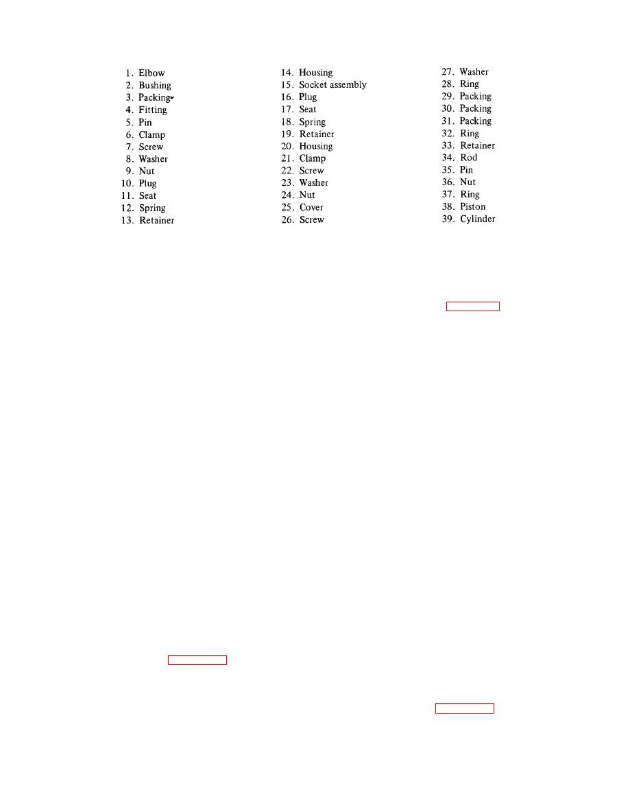
Figure 4-14. Booster cylinders (Sheet 2 of 2) |
|
||
| ||||||||||
|
|
 TM 55-1740-200-14
Figure 4-14. Booster cylinders (Sheet 2 of 2)
a. Remove rubber cover (1). Push horn button (2),
4-251. DISASSEMBLY. See figure 4-17 and dis-
turn one-third turn and remove button (2), cup (3),
assemble the distributor as follows:
spring (4) and contact (5).
a. Unclip the distributor cap. Remove cap and remove
b. Remove three screws (10) and remove plate (9) and
plunger (1) and spring (2) from cap (3). Remove rotor (4)
cable assembly. Remove terminal (6), ferrule (8), washer
and plate (5).
(12) and spring (11) from cable (7).
b. Remove two screws (6) and washers (7) and remove
c. Remove nut (35) and remove wheel (13), spring
breaker plate assembly. Remove screw (8), washer (9) and
(27) and spring seat (28). Remove bearing (29), and tubes
lock plate (10). Remove two screws (12) and washer (13)
(30 and 40).
and remove contact set (11). Remove two screws (15 and
16) and washer (17) and remove capacitor (14) from
plate (18).
d. Remove ten screws (15 and 16) and washers (17)
and remove cover (20) and gasket (21 ). Remove nut (18)
and setscrew (19) from cover (20). Remove levershaft
c. Remove felt wick (19) and retaining ring (20) and
remove cam (21) and spacer (22). Remove two springs
(25), remove two bearings (24) from levershaft (25).
(23) and weights (24) from shaft (32).
e. Remove four screws and washers and remove cover
(31) and shims (32, 33, 34) from housing (44). Remove
d. Remove two nuts (36), three washers (37, 38 and
39) and washer (40). Remove terminal screw (41),
two retaining rings (36), rings (37) and 28 balls (38) from
cam (39).
terminal (42), insulator (43) and washer (44).
e. Remove pin (30) and collar (31) and remove drive
f. Remove seal (41), two bearings (42) and cover (43)
from housing (44).
shaft (32) and thrust washer (35). Remove screw (27) and
two washers (28 and 29) and remove advance arm (26).
4-248. ELECTRICAL SYSTEM.
f. Remove oiler (45) and wick (46). Remove two
4-249. DISTRIBUTOR.
bearings (47) from base (48).
4-250. REMOVAL. See figure 4-16 and remove the
distributor as follows:
4 - 2 5 2 . IGNITION COIL.
a. Remove six spark plug wires (5, 6 and 7).
4 - 2 5 3 . REMOVAL. See figure 4-16 and remove two
nuts (16), washers (17), and remove coil (15).
b. Remove screw (14) and remove distributor (13).
4-43
|
|
Privacy Statement - Press Release - Copyright Information. - Contact Us |
