 |
|||
|
|
|||
|
Page Title:
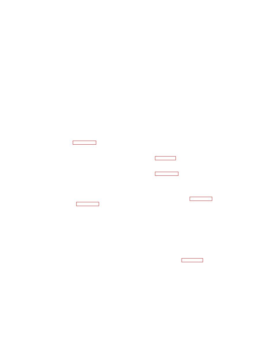
Figure 4-7. Deck, fender, and running board assembly (Sheet 1 of 2) |
|
||
| ||||||||||
|
|
 TM 55-1740-200-14
1. Rail
15. Washer
28. Washer
16. Washer
2. Nut
29. Nut
30. Running board
17. Nut
3. Washer
31. Screw
18. Nut
4. Catch
32. Washer
19. Fender
5. Screw
33. Nut
20. Screw
6. Screw
34. Washer
21. Screw
7. Washer
35. Clamp
22. Washer
8. Nut
36. Plate
23. Washer
9. Spacer
37. Screw
24. Nut
10. Grommet
38. Washer
25. Nut
11. Deck weldmen
39. Washer
26. Bracket
12. Screw
40. Nut
27. Screw
13. Screw
14. Washer
Figure 4-7. Deck, fender, and running board assembly (Sheet 1 of 2)
4-227. RELIEF VALVE.
4-230. FLOW CONTROL VALVE.
4-228. REMOVAL. See figure 4-8 and remove the
4-231. REMOVAL. Remove the flow control valve as
relief valve as follows:
follows:
NOTE
a. See figure 4-8 and remove four hose assemblies (4,
28, 29 and 30) and union (31).
Provide proper receptacle and drain hydraulic
reservoir prior to valve removal.
b. See figure 4-11 and remove two screws (2), two
screws (3), four washers (4), and nuts (5). Remove
a. Remove connecting hoses (26 and 5).
assembled valve and bracket (1) from tractor.
b. Remove valve (27) from pump (21).
4-23 2. DISASSEMBLY. See figure 4-11 and dis-
assemble the flow control valve as follows:
4-229. DISASSEMBLY. See figure 410 and dis-
assemble the relief valve as follows:
a. Remove tee (6), two elbows (7), and three bushings
(8).
a. Remove bushing (1), elbow (2), and nipple (3).
Remove two elbows (5), plug (4), cross (6), and nipple
b. Remove retaining ring (9) and remove valve (10)
(7).
and spring (11) from valve body (12).
b. Remove packing (10) from bushing (9). Remove
bushing (9) with piston attached from body (21). Remove
nut (8) from thread part of piston (11). Remove packing
(12) from piston (11) remove bushing (9) completely
4-234. REMOVAL. See figure 4-8 and remove the rear
from piston.
cam and valve assembly as follows:
c. Remove two seats (14) and balls (13) on spring (15)
a. Remove clamp (33) and four hose assemblies (28,
from body. Disassemble two seats (14), balls (13), and
30, 65, and 66). Remove two screws (102), washers
springs (15).
(103), and nuts (104) and remove shield (101).
d. Remove packing (17) and restrictor (16) from valve
b. Remove nut (92) and washer (93). Remove two
body (21) and disassemble. Remove valve from valve
screws (106), washers (107), and nuts (108) and remove
body (21). Remove packings (17 and 19) and retainers
cam and valve assembly (105).
(18) next to packing (19).
4-31
|
|
Privacy Statement - Press Release - Copyright Information. - Contact Us |
