 |
|||
|
|
|||
|
Page Title:
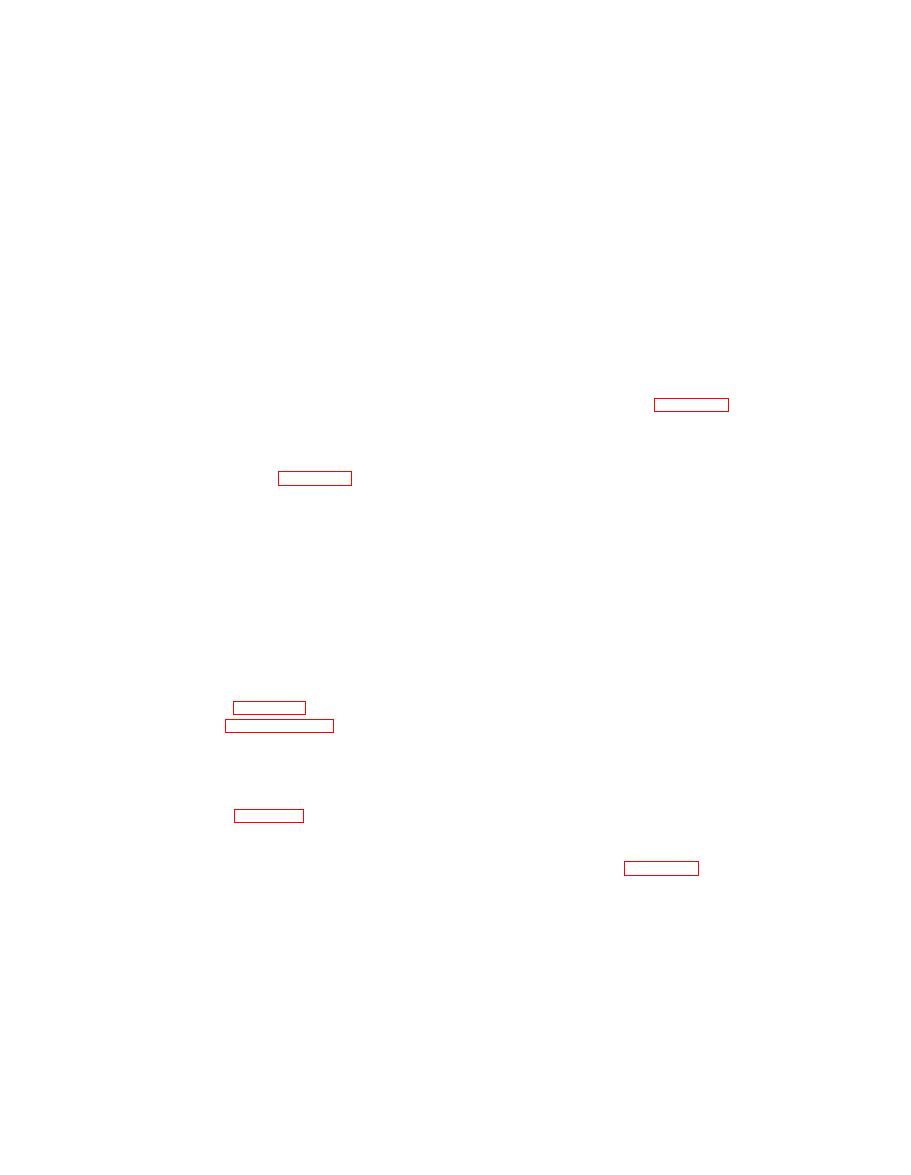
Figure 45. Hood assembly (Sheet 2 of 2) |
|
||
| ||||||||||
|
|
 TM 55-1740-200-14
1. Screw
8. Strike
15.
Panel
2. Washer
9. Rivet
16.
Panel
3. Nut
10. Handle
17.
Panel
4. Fastener
11. Rivet
18.
Screw
5. Rivet
12. Rod
19.
Washer
6. Panel
13. Panel
20.
Nut
7. Panel
14. Panel
Figure 45. Hood assembly (Sheet 2 of 2)
4-218. DECK, FENDERS, AND RUNNING BOARDS.
b. Remove two screws (18), washers (19), and nuts
(20). Remove hood assembly.
4-219. REMOVAL. Refer to figure 4-7 and remove the
4-214. DISASSEMBLY. Disassemble the hood as
deck, fenders, and running boards as follows:
follows:
a. Remove two screws (20), washers (22), and nuts
(24). Remove two screws (21), washers (23), and nuts
a. Remove eight rivets (5, figure 45) and remove
(25). Remove front fender (19).
four fasteners (4) from two panels (6 and 7).
b. Remove eight rivets (9) and remove four catches
b. Remove two screws (37), washers (38), and nuts
(8). Remove four rivets (11) and remove two handles
(40) then remove plate cover (36). Remove four screws
(10).
(31), washers (32), and nuts (33). Remove two screws
(13), washers (15), and nuts (17) then remove running
c. Remove four rods (12) and remove two louvered
board (30).
panels (13 and 14) and two" curved panels (15 and 16)
from center panel (17).
c. Remove grommet (10). Remove eight nuts (2) and
washers (3) and remove two hand rails (1).
4-215. DOOR ASSEMBLY.
d. Remove two screws (6) and nuts (8) and remove
4-216. REMOVAL. See figure 4-6 and remove the door
catch (4) and spacer (9) from box.
assembly as outlined in paragraph 4-207a.
e. Remove eight screws (12), four wedge washers (14),
4-217. DISASSEMBLY. Disassemble the vehicle door as
eight washers (15) and nuts (17) and remove rear deck.
follows:
4-220. DISASSEMBLY. None required.
a. Remove screw (2, figure 4-6), washer (3), handle
4-221. STEERING SYSTEM.
(1), spring (4), and plate (5). Remove four screws (6) and
nuts (7) then remove latch (12), shims (11), and handle
4-222. REMOVAL. See figure 4-8 and remove steering
assembly. Remove retaining ring (8) and shaft (9) from
system piping and components as follows:
plate (10).
NOTE
b. Remove nine screws (14), washers (15), washers
(16). Remove interior panel assembly. Remove glass (17)
Provide proper receptacle and drain hydraulic
and channel (18). Remove six screws (20), washers (21),
fluid prior to removal.
nuts (22). Remove regulator (19) from panel (13).
a. Remove three hose assemblies (1, 4 and 5), one
c. Remove weatherstrips (23 and 24). Remove four
adapter (2), two unions (6) and three elbows (3 and 7).
screws (26), two screws (27), six washers (28), six nuts
Remove breather (11 ). Remove four screws (8), washers
(29). Remove three hinges (25) and shims (30) from
exterior panel (31).
(9) and nuts (10) and remove reservoir tank (12).
4-27
|
|
Privacy Statement - Press Release - Copyright Information. - Contact Us |
