 |
|||
|
|
|||
|
|
|||
| ||||||||||
|
|
 TM 55-1740-200-14
brackets for frame mounted components are extra heavy
1-54. MECHANICAL TRANSMISSION.
to provide required tractor weight, heavy duty service life
and stability for mounted components. Medium duty,
1-55. The mechanical transmission (10), attached to the
non-quick release pintle assemblies are mounted on the
rear of the hydraulic transmission, is a standard,
front and rear of the tractor.
commercial, five-speed gearbox with second through fifth
gear synchronized. Gear selection is made by manual shift
after disengaging the clutch.
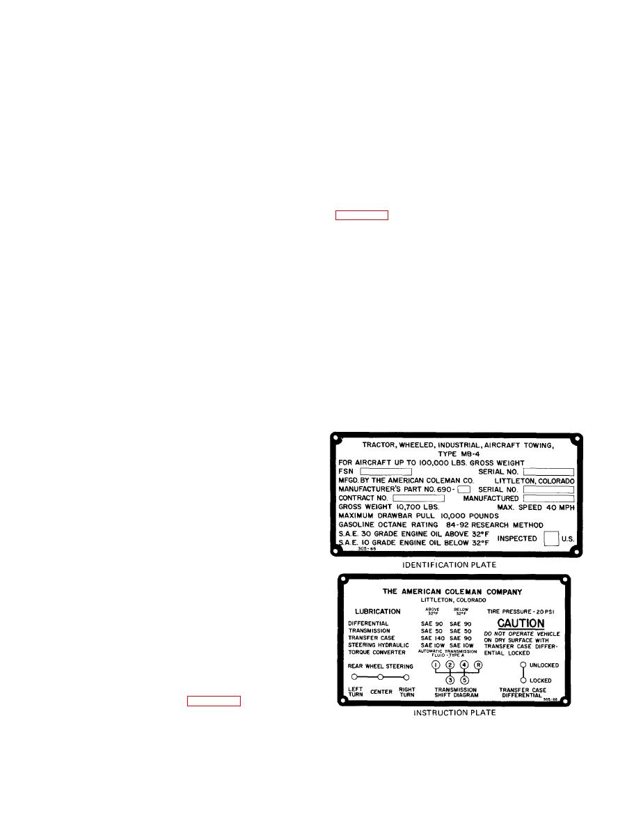
1-67. IDENTIFICATION AND INSTRUCTION
PLATES.
1-56. PROPELLER SHAFT INSTALLATION.
1-68. The type MB-4 towing tractor identification plate
1-57. Standard commercial propeller shafts connect the
transmission to the transfer case input shaft and connect
number and serial number, manufacturer name and
the front and rear output shafts of the transfer case with
address, manufacturer's part number and serial number,
the front and rear axles respectively.
contract number, manufactured date, gross weight,
maximum speed, maximum drawbar pull, gasoline octane
1-58. TRANSFER-TRANSMISSION ASSEMBLY.
rating, engine oil grade for above and below 32F
stamp impression. The instruction plate provides
1-59. The transfer-transmission assembly (11), sometime
applicable data.
referred to as the transfer case, is a single-speed gearbox
incorporating a manually-locking type center differential
between the front and rear output shafts. The center
1-69. DEVIATIONS IN MODELS.
differential action can be locked out by means of a lever
located to the driver's right. The transfer-transmission
assembly further multiplies the engine torque and
1-70. This manual covers only the type MB-4 Towing
transfers it to the front and rear axles through the
Tractor, Model Number G-40, part numbers 690-lB and
propeller shafts.
690-1B1. Existing unit differences shall be designated C
or D code.
1-60. BRAKE SYSTEM.
1-61. The service brake system (12) uses hydraulically
operated brake shoes and incorporates a vacuum booster.
The system has sufficient capacity to lock the wheels
when the brakes are applied at a maximum speed of 30
mph on dry concrete.
1-62. VACUUM BOOSTER. The vacuum booster is
controlled by hydraulic pressure developed within the
brake master cylinder of the vehicle.
1-63. AXLE INSTALLATION.
1-64. The front and rear axles (13) are identical, driving,
center-point steering type to reduce steering effort. The
one-piece axle shaft is easily removed without wheel
disassembly to facilitate quick removal of the axle
differential carrier assembly, which is a commercial,
high-production assembly.
1-65. FRAME AND BRACKETS ASSEMBLY.
1-66. The frame rails (14, figure 1-2) are made of
structural channel to provide strength and rigidity for the
tractor. Heavy frame end plates provide additional rigidity
AV 008935
and stable mounting for the counterweights. Various
|
|
Privacy Statement - Press Release - Copyright Information. - Contact Us |
