 |
|||
|
|
|||
|
|
|||
| ||||||||||
|
|
 TM 5-2420-224-34
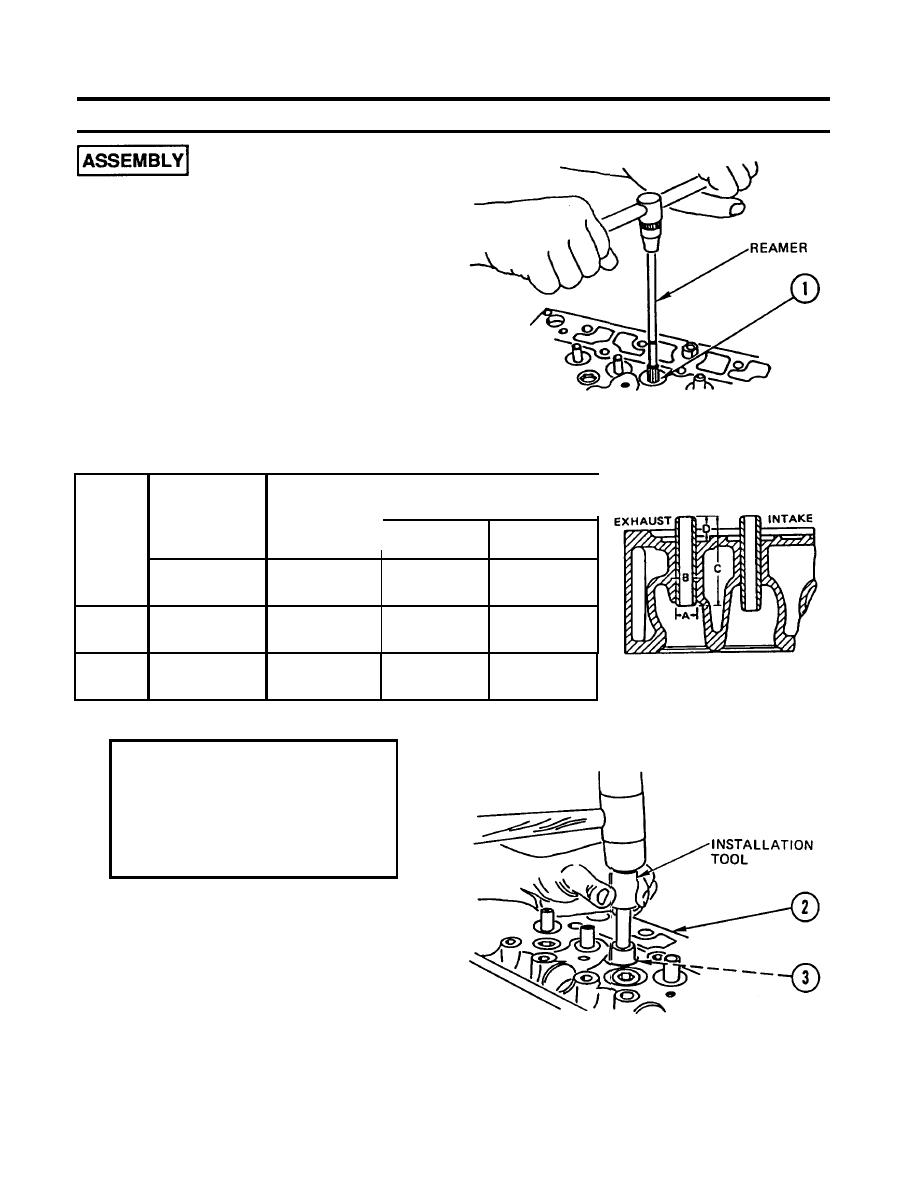
CYLINDER HEAD REPAIR (CONT)
1.
USING REAMER, REAM valve guide BORE
(1) to next higher repair stage as shown in
following table.
Valve Guide Specifications
Valve Guide
Valve Guide Inside
Bore in
Diameter B, Final
Cylinder
Outside
Diameter A,
Head A
Repair
Intake
Interference Fit
Stage
In.
In.
In.
In.
(mm)
(mm)
(mm)
(mm)
0.5906-0.5913 0.5917-0.5924
Standard
0.3543-0.3552 0.3937-0.3946
(15.000-15.018) (15.026-15.046)
(9.000-9.022) (10.000-10.022)
0.5984-0.5991
Stage I
0.5995-0.6002 0.3543-0.3552 0.3937-0.3946
(15.200-15.218) (1 5.228-15.246) (9.000-9.022) (10.000-1 0.022)
WARNING
Cylinder head will be hot
enough to burn you on contact.
Wear heat-resistant gloves
when handling hot cylinder
head.
2.
HEAT cylinder HEAD (2) to 212F (100C)
and FREEZE new valve GUIDES.
APPLY light COAT of LUBRICATING OIL to
3.
new valve GUIDES (3).
4.
USING INSTALLATION TOOL, INSTALL valve
GUIDES (3) in cylinder head (2).
13-8
|
|
Privacy Statement - Press Release - Copyright Information. - Contact Us |
