 |
|||
|
|
|||
|
|
|||
| ||||||||||
|
|
 TM 5-2420-224-34
TILT
AND
LATCH
CONTROL
VALVE
REPLACEMENT
AND
ADJUSTMENT
(CONT)
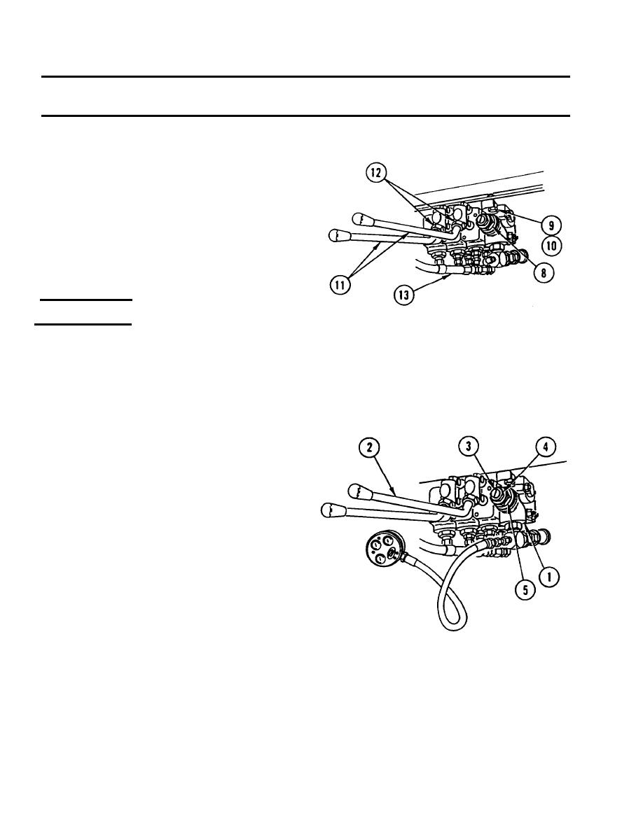
INSTALL VALVE (8), three washers (9), and
3.
three screws (10).
INSTALL two HANDLES (11) and tighten two
4.
lock nuts (12).
REMOVE CAPS or PLUGS. CONNECT eight
5.
HOSES (13).
PERFORM ADJUSTMENT.
6.
ADJUSTMENT
NOTE
Vehicle must be parked on level
surface with front loader (SEE) or
f o r k l i f t (HMMH) resting on flat
surface, and parking brake must
be set.
1.
Connect 0-5000 psi (0-352.1 bar) gage to test
port on inlet section of control valve (1).
2.
Perform following to achieve hydraulic oil
operating temperature:
a. Start and run engine at 2000 rpm
using hand throttle.
b. Place lock control lever (2) in u p
position and hold for 15 seconds.
c. Place lock control lever (2) in neutral
position for 30 seconds.
d. Repeat until hydraulic oil cooler turns
on.
While maintaining engine speed of 2000 rpm,
3.
place lock control lever (2) in up position and
read pressure gage. Pressure must be 2450
psi (172.5 bar). If reading is not correct,
adjust control valve (1) according to following:
a. While holding adjusting screw (3),
loosen lock nut (4) on main relief
v a l v e (5) on inlet section of control
valve (1).
11-8
|
|
Privacy Statement - Press Release - Copyright Information. - Contact Us |
