 |
|||
|
|
|||
|
|
|||
| ||||||||||
|
|
 TM 5-2420-224-34
BRAKE PRESSURE REGULATOR (ALB VALVE) ADJUSTMENT (CONT)
NOTE
I f adjustment setting cannot be
obtained and gage readings
fluctuate after rechecking, it may
be necessary to bleed brake
system (TM 5-2420-224-20) and
repeat Adjustment steps 1 thru 5.
Press brake pedal several times to activate
5.
brake system. Recheck gage reading for
proper pressure setting.
CAUTION
B e f o r e performing steps 6 thru
13, ALB fail-safe pressure
setting must be completed to
p r e v e n t damage to equipment.
Install spare tire (TM 5-2420-224-20).
6.
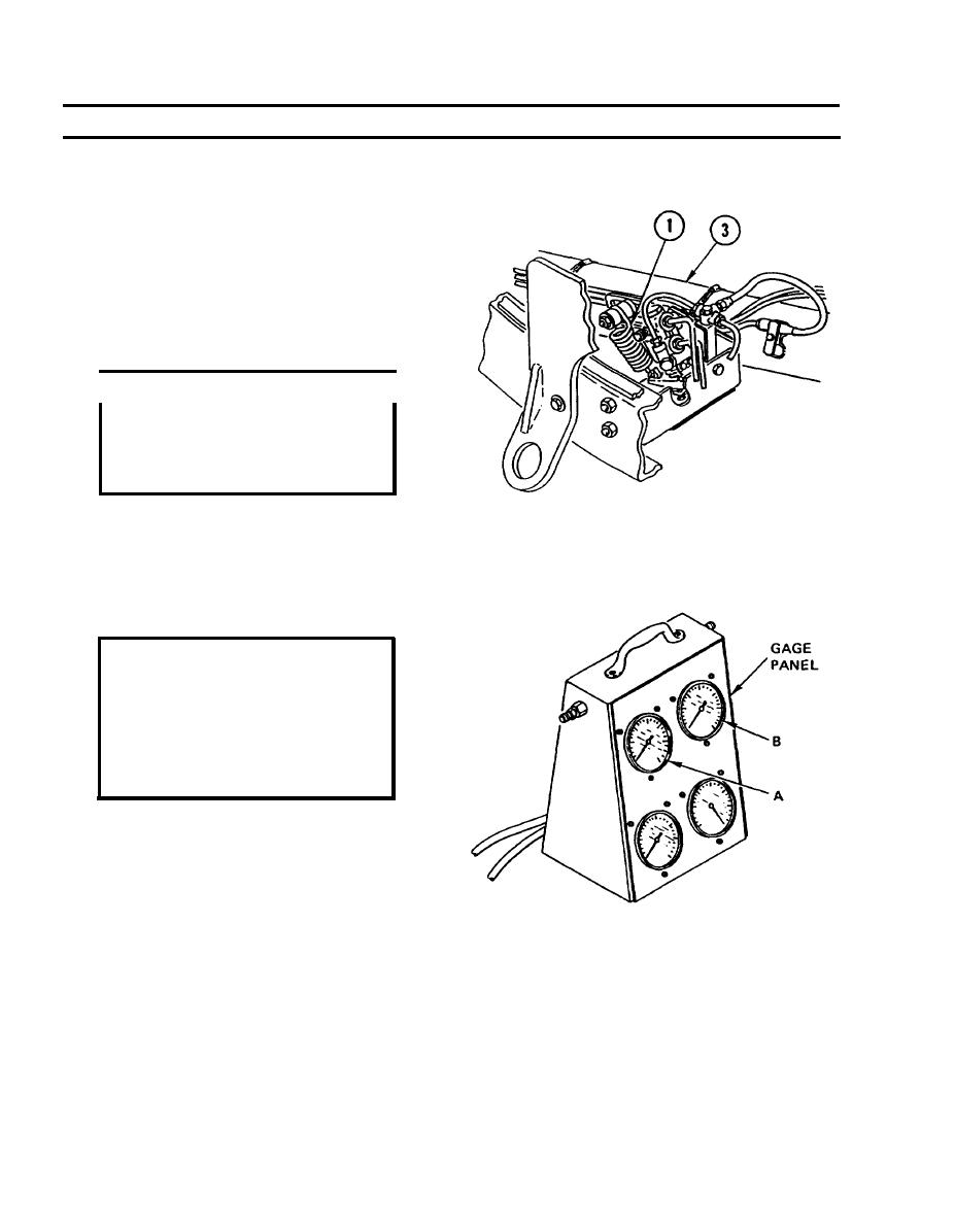
7.
If removed, install control spring (1) to rear
torque tube (3) or retract outriggers.
Place backhoe (SEE) or crane (HMMH) in
8.
transport position (TM 5-2420-224-10).
CAUTION
Make sure air pressure of
vehicle brake system is not
below
90
psi
(6
bar)
as
i n d i c a t e d on air pressure gage
l o c a t e d on instrument panel to
p r e v e n t damage to equipment.
NOTE
Gage A indicates pressure of
modulated circuit 1. This pressure
is proportionate to rear axle load
with vehicle in transport position.
Position gage panel so gages can be read
9.
accurately. Slowly press brake pedal until full
pedal pressure is achieved. Both pressure
gages should rise until gage A reads modulated
rear axle load pressure setting of 1352 psi
(92 bar). Tolerance of 44 psi (3 bar) is
permissible. Gage B of unmodulated circuit
should read approximately 1924-2072 psi
(130-140 bar).
7-8
|
|
Privacy Statement - Press Release - Copyright Information. - Contact Us |
