 |
|||
|
|
|||
|
Page Title:
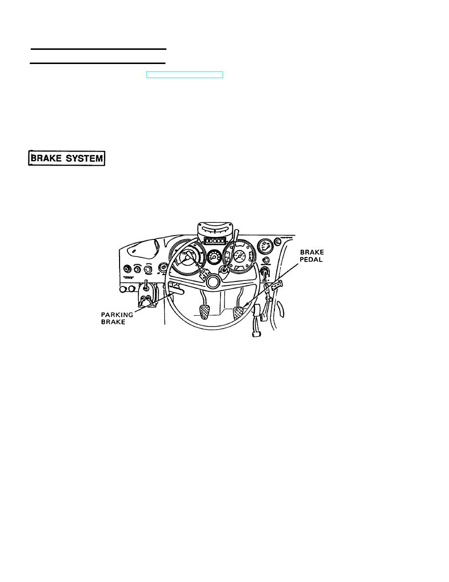
Brake System |
|
||
| ||||||||||
|
|
 TM 5-2420-224-20-1
ELECTRICAL SYSTEM (CONT)
Switches and Gages. Refer to TM 5-2420-224-10 for the locations and detailed descriptions of
the switches and gages.
Sending Units. The intermediate speed indicator is located on the right side of the
transmission; the parking brake indicator is located on the cable lever at the center of the rear
axle; the low air warning indicator is located on the air line to the trailer air brake valve; the
Power Take-Off (PTO) indicator is located on the left side of the transmission housing at the PTO
housing; the fuel level sending indicator is located on the right side top of the fuel tank; the
neutral start switch indicator is located under the clutch pedal on the left side of the cab.
The vehicle is equipped with air-assisted hydraulic brakes. The dual circuit brake system utilizes
four-wheel disc brakes with two calipers on each front wheel, one on each rear wheel, and a
cable-operated parking brake at the rear.
Service Brakes. The service brakes consist of the brake booster, master cylinder, brake pedal,
brake pads and discs, service brake warning light, and air pressure warning alarm.
Parking Brake. A cable-actuated cam acts on the caliper brake on the rear wheel when the
lever is pulled. There is also a parking brake warning light.
|
|
Privacy Statement - Press Release - Copyright Information. - Contact Us |
