|
| |
TM 5-2420-222-34
15-3.
BACKHOE SWING FRAME MAINTENANCE (Con’t).
NOTE
Perform steps 2 through 4 only If sleeve bushings were removed.
2.
Using ball-peen hammer and brass drift, tap two sleeve bushings (26) In swing frame (6).
3.
Using ball-peen hammer and brass drift, tap two sleeve bushings (25) in swing frame (6).
4.
Using ball-peen hammer and brass drift, tap two sleeve bushings (23) in swing frame (6).
5.
Install three new grease fittings (22) in swing frame (6).
f.
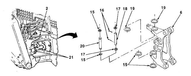
INSTALLATION
1.
Install four spacers or washers (19) on swing frame (6) and main frame (2).
WARNING
Use extreme caution when handling heavy parts. Lifting device is required when
parts weigh over 50 lb. (23 kg) for a single person lift, over 100 lb. (45 kg) for a two
person lift, and over 150 lb. (68 kg) for a three or more person lift. Keep clear of
heavy parts supported only by lifting device. Failure to follow this warning may
cause serious injury or death to personnel.
2.
Using lifting device, position swing frame (6) and four washers (19) in place on main frame (2) with pin holes
alined.
3.
Install two pins (18 or 20) in swing frame (6) and swing cylinders (21).
NOTE
Some swing frames have linkage pins retained by cotter pins; some have linkage
pins retained by retaining rings. For swing frames equipped with cotter pins,
perform step 4 and skip step 5. For swing frames equipped with retaining rings,
skip step 4 and perform step 5.
4.
Install four washers (17) and new cotter pins (16) in two pins (18).
5.
Install four retaining rings (15) on two pins (20).
TA701644
15-15
|