|
| |
TM 5-2420-222-34
14-16.
LOADER BUCKET RELIEF VALVES MAINTENANCE (Con’t).
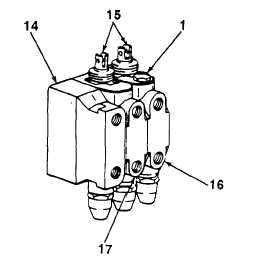
g. ADJUSTMENT
1.
If installed, remove loader control valve assembly (see TM 5-2420-222-20).
2.
Connect proof pressure tester to valve cap (14).
3.
Using four 34 in. -14 NPT pipe plugs, plug boom valve (17) and
0bucket valve (16).
4.
Using proof pressure tester, pump up hydraulic pressure to 1800 psi
(12,411 kPa) and check for leaks. Tighten all leaking connections.
If leaking does not stop, release pressure and replace defective
part.
NOTE
All relief valves are adjusted the same
way. Repeat steps 5 through 9 for other
relief valve as required.
5.
Push clevis rod end (15) down to check top relief valve (1) or pull up
to check bottom relief valve.
WARNING
Relief valves are stamped with pressure limit. Bucket (lower) relief valve pressure
limit is 1500 psi (10,343 kPa). Bucket (raise) relief valve pressure limit is 2750 psi
(18,961 kPa). Do not exceed stamped pressure limit. Serious injury to personnel
may result.
6.
Using proof pressure tester, pump up hydraulic pressure until relief valve (1) opens or pressure limit of relief valve
is reached.
NOTE
If relief valve opening pressure is correct, skip steps 7 through 9.
7.
Remove and disassemble relief valve (see subparagraphs a and b).
8.
If opening pressure was more than specified, remove shims (5). If opening pressure was less than specified limit,
add shims as required.
9.
Assemble, install, and adjust relief valve (see subparagraphs e, f, and g).
FOLLOW-ON TASKS:
•
Install loader control valve assembly (see TM 5-2420-222-20).
TA701606
14-83
|