|
| |
TM 5-2420-222-34
14-3.
HYDRAULIC PUMP ASSEMBLY MAINTENANCE (Con’t).
19.
Check transmission hydraulic fluid level. Add hydraulic fluid as
required (see LO 5-2420-222-12).
20.
Repeat steps 16 and 17.
21.
Check reading on hydraulic system tester. Pressure must read
2300-2400 psi (15,859-16,548 kPa). If pressure reading is
correct, skip step 22.
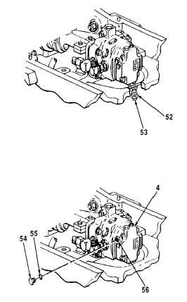
22.
Loosen nut (53) and turn adjusting screw (52) clockwise to
increase or counterclockwise to decrease system pressure until
reading on hydraulic system tester reads 2300-2400 psi (15,859-
16,548 kPa).
23.
Adjust engine speed to 1800 rpm (see TM 5-2420-222-10).
24.
Adjust hydraulic system tester control valve until pressure gage
reads 2000 psi (13,790 kPa). Hydraulic pump flow must be 25
gpm (95 lpm). If pump flow is okay, skip step 25 and go to step
26.
25.
Release hydraulic system pressure (see TM 5- 2420-222-20).
26.
Remove plug (54) from stroke control valve (4). Remove
preformed packing (55) from plug. Discard preformed packing.
27.
Connect multirange pressure gage to stroke control valve inlet
pressure tap (56).
28.
Check transmission hydraulic fluid level (see LO 5-2420-222-12).
29.
Start engine assembly and run at 2500 rpm until operating temperature is 170°F-190°F (77C-88C) (see TM 5-
2420-222-10).
30.
Adjust engine speed to 1800 rpm (see TM 5-2420-222-10).
31.
Check inlet pressure reading on multirange pressure gage. Pressure reading must be 5 psi (34 kPa). If inlet
pressure reading is correct but hydraulic pump flow is below 25 gpm (95 Ipm) replace hydraulic pump.
32.
Shut down engine assembly (see TM 5-2420-222-10).
33.
Release hydraulic system pressure (see TM 5-2420-222-20).
34.
Remove multirange pressure gage from stroke control valve inlet pressure tap (56).
35.
Install new preformed packing (55) on plug (54) and install plug In stroke control valve (4).
TA701559
14-24
|