|
| |
TM 5-2420-222-34
14-3.
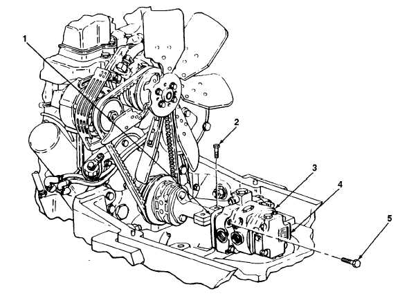
HYDRAULIC PUMP ASSEMBLY MAINTENANCE (Con’t).
3.
Aline hydraulic pump (3) and stroke control valve (4) on bracket (1) and install four screws (5).
4.
Tighten two screws 92) on hydraulic pump drive shaft.
f.
ADJUSTMENT
NOTE
Use a drain pan to catch fluid when disconnecting oil lines and plugs. Clean up all
spills.
1.
Install hydraulic pump stroke control valve solenoid (see paragraph 14-7).
2.
Connect oil cooler line (see TM 5-2420-222-20).
3.
Connect speed gear assembly (reverser) seal drain line (see TM 5-2420-222-20).
4.
Connect clutch control valve inlet oil line (see TM 5-2420-222-20).
5.
Connect pressure control valve oil line (see TM 5-2420-222-20).
6.
Install fuel tank (see TM 5-2420-222-20).
7.
Check transmission hydraulic fluid level (see LO 5-2420-222-12).
TA701557
14-22
|