|
| |
TM 5-2420-222-20-2
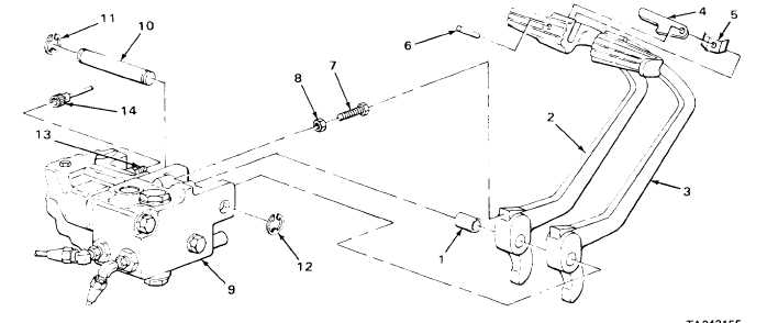
SERVICE BRAKE PEDALS - CONTINUED
ACTION
LOCATION
ITEM
REMARKS
18. Brake pedal (2),
Spring pin (6)
a.
Aline pin holes in pedal (2), bar (4),
bar (4) and leaf
and spring (5).
spring (5)
b.
Using 1-pound head ball-peen hammer,
tap in.
c.
Take pedal (2) out of machinist’s vise.
19. Two screws (7)
Two nuts (8)
Screw on part way.
INSTALLATION
20. Hydraulic
Two screws (7)
Screw in finger tight.
cylinder (9)
and nuts (8)
21. Shaft (10)
Ring (11)
Using retaining ring pliers, place in
position.
22. Hydraulic
Two brake pedals
Place in position.
cylinder (9)
(2 and 3) with
assembled parts
23. Hydraulic cylinder
Shaft (10) with
a.
Aline holes in hydraulic cylinder (9)
(9) and two brake
assembled retaining
and two pedals (2 and 3).
pedals (2 and 3)
ring (11)
b.
Using plastic-faced hammer, tap in.
24. Hydraulic cylinder
Ring (12)
Using retaining ring pliers, place in
(9) and shaft (10)
position.
25. Union (13)
Line (14)
Screw on and tighten using 7/16-inch open-
end wrench.
2-895
|