|
| |
TM 5-2420-222-20-2
SPEED GEAR ASSEMBLY (REVERSER) CONTROL LEVER LINKAGE - CONTINUED
ACTION
LOCATION
ITEM
REMARKS
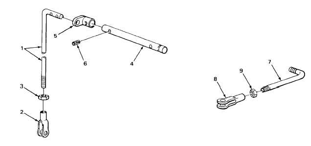
27.
Control lever rod
Nut (3)
a.
Using 9/16-inch open-end wrench and
(1) and yoke (2)
0 to 1.322-inch adjustable wrench,
tighten until seated against yoke (2).
b.
Take rod (1) out of machinist’s vise.
NOTE
Steps 27 and 28 only apply to loader backhoes with Serial Numbers 235786 thru 235999.
28.
Shaft (4)
Control lever
a.
Place shaft (4) in machinist’s vise.
arm (5)
b.
Place in position, lining up pin holes.
29.
Shaft (4) and
Groove pin (6)
a.
Using 1-pound ball-peen hammer
control lever
tap in.
arm (5)
b.
Take shaft (4) out of machinist’s vise.
30.
Link (7)
Adjustable yoke (8)
a.
Place link (7) in machinist’s vise.
and nut (9)
b.
Screw on until number of exposed
threads on link (7) and relative
position of yoke (8) are same as
noted in disassembly.
31.
Link (7) and
Nut (9)
a.
Using 1/2-inch open-end wrench and 0
adjustable yoke (8)
to 1.322-inch adjustable wrench,
tighten until seated against yoke (8).
b.
Take link (7) out of machinist’s vise.
TA243120
2-821
|