 |
|||
|
|
|||
|
|
|||
| ||||||||||
|
|
 TM 5-2420-222-20-1
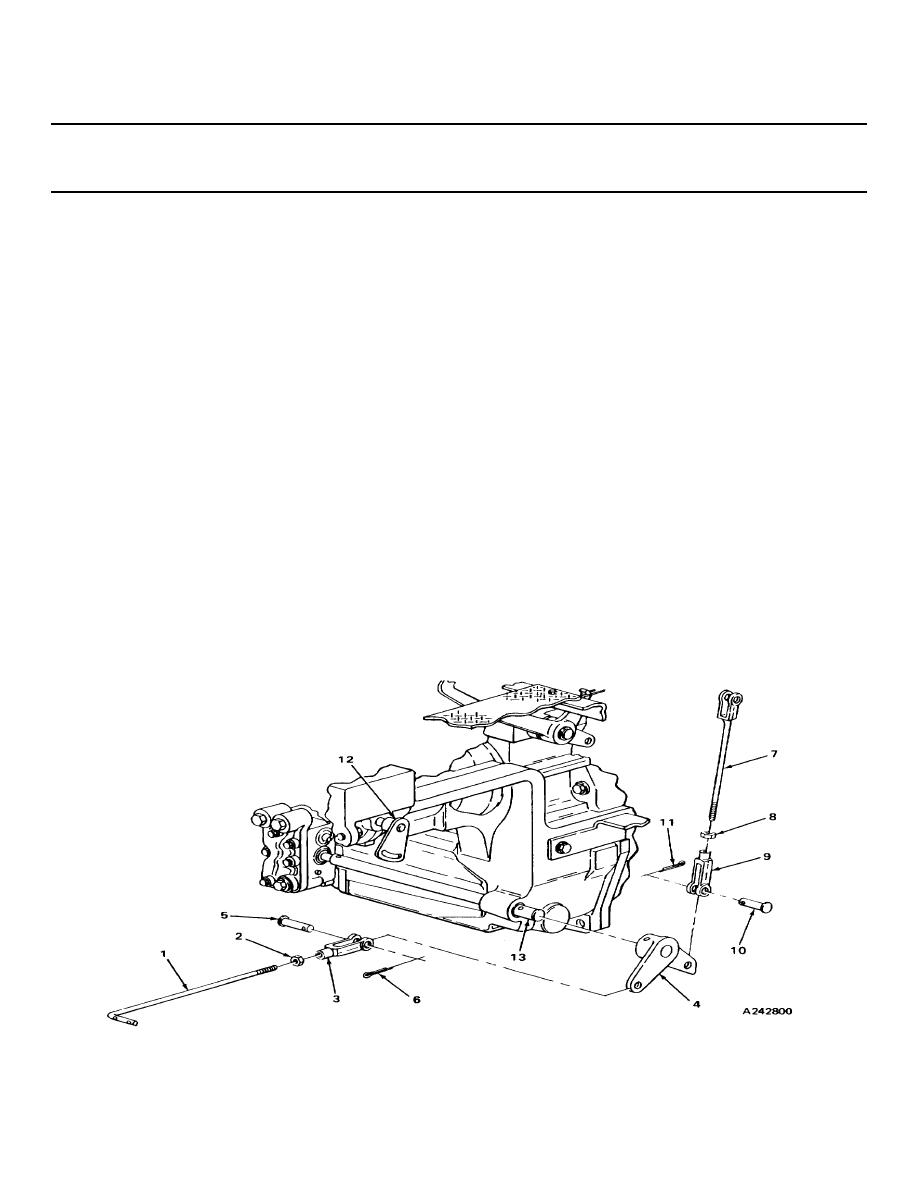
CLUTCH PEDAL LINKAGE - CONTINUED
ACTION
LOCATION
ITEM
REMARKS
29.
Continued
b. Screw on until same number of exposed
threads are showing on rod end (7) and
relative position of yoke or clevis (9) is
same as noted during disassembly.
30.
Rod end (7) and
Nut (8)
a. Using 9/16-inch open-end and, 0 to
yoke or clevis (9)
1.322-inch adjustable wrenches,
tighten until seated against yoke or
clevis (9).
b. Take rod end (7) out of machinist's
vise with vise jaw caps.
31.
Bellcrank (4)
Yoke or clevis (9)
Place In position.
32.
Yoke or clevis (9)
Pin (10)
Slide in.
and bellcrank (4)
33.
Pin (10) and
New cotter pin (11)
a. Push in.
yoke or clevis (9)
b. Using slip-joint pliers, bend ends back.
INSTALLATION
34.
Lever (12) and
Rod (1) and
Slide on.
shaft (13)
bellcrank (4) with
assembled parts
2-191
|
|
Privacy Statement - Press Release - Copyright Information. - Contact Us |
