 |
|||
|
|
|||
|
|
|||
| ||||||||||
|
|
 TM5-241O-237-34
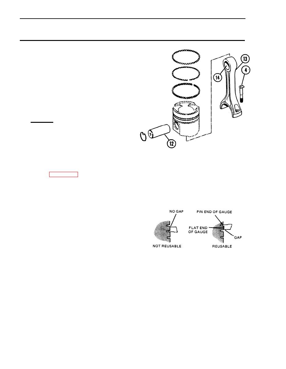
3-18. PISTONS, CONNECTING RODS, PISTON PINS AND RINGS -
REPLACE/REPAIR (Cont'd)
(12) Check the piston pin bearing bore
diameter after the bearing (14)
is installed. The correct
dimension is 1.70120.0003 in.
The maximum permissible clearance
between the bearing and piston
pin (12) must not be more than
0.003 in.
(13) If necessary, remove two
capscrews (4) from connecting
rod (13).
c.
Assembly
(1) If it was necessary to remove two
capscrews (4), install them on
connecting rod (13).
(2) When old pistons are used, clean
the piston grooves with an
acceptable ring groove tool.
(3) See Table 3-4 for correct piston
and ring clearances.
(4) It is necessary to measure the
grooves in pistons with a
Keystone piston ring groove
gage. Put the pin end of in the
groove at four places around the
Do this to both
circumference.
grooves. The flat edge of the
gage must be between grooves for
the top ring and intermediate
ring. If there is clearance
between the flat edge of the
gage and the piston at all test
locations, for both grooves,
reuse the piston. If the flat
edge is in contact with the
piston, at any of the test
locations, do not reuse the
piston. Install a new piston.
3-80
|
|
Privacy Statement - Press Release - Copyright Information. - Contact Us |
