 |
|||
|
|
|||
|
|
|||
| ||||||||||
|
|
 TM 5-2410-237-23
WINCH ASSEMBLY REPAIR - CONTINUED
0245 19
ASSEMBLY - CONTINUED
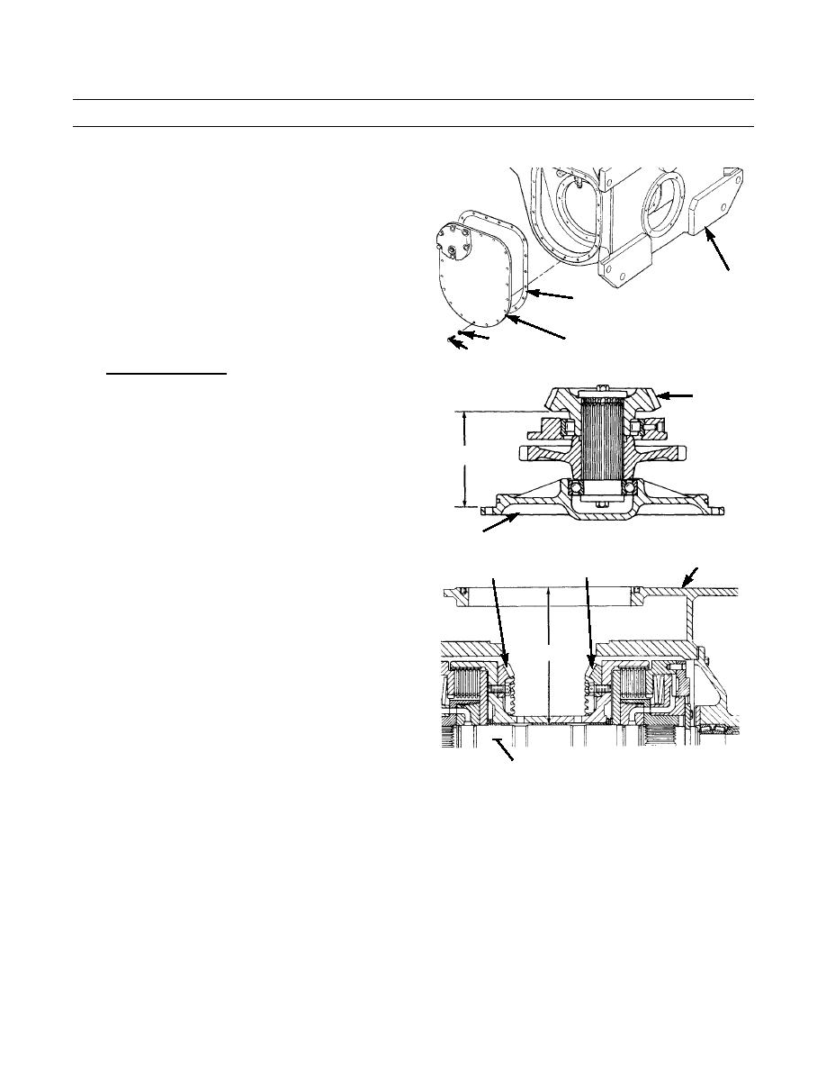
bg. Install new gasket (154) and access cover (153)
to case (5) with 15 new lockwashers (152) and
bolts (151). Tighten bolts to 36 lb-ft (49 Nm).
5
154
152
153
421-0219
151
3.
Install Winch Pinion.
a.
Remove three bolts (115), bearing cage (116)
127
and pinion assembly from case (5).
b.
Measure and record dimension (B) between
mounting surface of bearing cage (116) and back
B
face of pinion gear (127).
PINION ASSEMBLY
421-0317
116
c.
Measure and record dimension (C) between face
5
200
200
of case (5) and clutch shaft (155) through gap
between two clutch housings.
C
421-0318
155
d.
Calculate difference between dimension (B) in step b and dimension (C) in step c.
e.
Subtract difference found in step d from 4.375 in. (111.13 mm), to determine thickness of shims (117) needed to
obtain correct free movement (backlash) between pinion gear (127) and bevel gears (200), when pinion assembly
is installed.
0245 19-29
Change 1
|
|
Privacy Statement - Press Release - Copyright Information. - Contact Us |
