 |
|||
|
|
|||
|
|
|||
| ||||||||||
|
|
 TM 5-2410-237-23
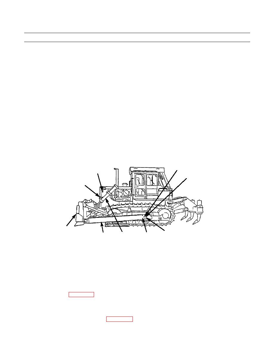
BLADE AND PUSHARM ASSEMBLY REPLACEMENT - CONTINUED
0235 00
REMOVAL - CONTINUED
CAUTION
When retracting cylinders, have an assistant guide rod to prevent damage to rod from contact with track or
other parts of tractor.
12.
Retract both lift cylinders (25).
13.
Remove pin (27) from post (28). Line up bracket (29) on cylinder with post. Install bracket on post and secure with pin.
14.
Repeat step 13 for other cylinder, and secure both cylinder rods in position with wire.
15.
Remove two nuts (30), bolts (31), lockwashers (32) and cap (33) from pusharm (34). Discard lockwashers.
16.
Repeat step 15 on other pusharm (34).
WARNING
Use extreme caution and ground guide assistance to prevent injury or death.
17.
Carefully back tractor away from pusharm and blade assembly.
35
27,28
33
29
26
387-776
31,32
25
34
30
INSTALLATION
WARNING
Use extreme caution and ground guide assistance to prevent injury or death.
1.
Drive tractor up to blade and pusharm assembly. Have assistant guide tractor into position (TM 5-2410-237-10).
2.
Place cap (33) in position on trunnion (35) and install two bolts (31). New lockwashers (32), and nuts (30). Tighten nuts
IAW torque limits (WP 0245 00). Repeat step for other pusharm (34).
3.
Remove wires securing rods to lift cylinders (25). Remove pins (27) from posts (28). Remove lift cylinders and brackets
(29) from posts. Reinstall pins in posts.
4.
Connect lift cylinders (25) to blade (26) (WP 0220 00).
0235 00-3
|
|
Privacy Statement - Press Release - Copyright Information. - Contact Us |
